Solid-state laser device and photoacoustic measurement device

a laser device and laser beam technology, applied in the direction of instruments, specific gravity measurement, active medium materials, etc., can solve the problems of increasing the size of the device, difficult to sufficiently reduce the pulse width of the pulsed laser beam, and the structure of the device is complicated, so as to reduce the distance between the end surface and the end surface. , the effect of reducing the distance between the end surface and the configuration is simpl

Active Publication Date: 2016-06-30
FUJIFILM CORP
View PDF5 Cites 2 Cited by
  • Summary
  • Abstract
  • Description
  • Claims
  • Application Information

AI Technical Summary

Benefits of technology

[0034]In this way, for pulling the rod-shaped portion of the excitation light source out of the laser chamber, it is not necessary to secure the space for moving and pulling the optical element out; therefore, the solid-state laser device of the invention has a simpler configuration compared to a solid-state laser device which has a configuration for moving the optical element.
[0035]The optical element is disposed such that at least a part of the optical element and at least a part of the rod-shaped portion are at the same position in the longitudinal di

Problems solved by technology

In this way, if the resonator mirror is disposed at a large distance from the end surface of the solid-state laser medium, and the resonator length is large, the device is increased in size, and in a case where pulse oscillation is caused, it is difficult to sufficiently reduce the pulse width of the pulsed la

Method used


Image

  • Solid-state laser device and photoacoustic measurement device
  • Solid-state laser device and photoacoustic measurement device
  • Solid-state laser device and photoacoustic measurement device

Examples


first embodiment

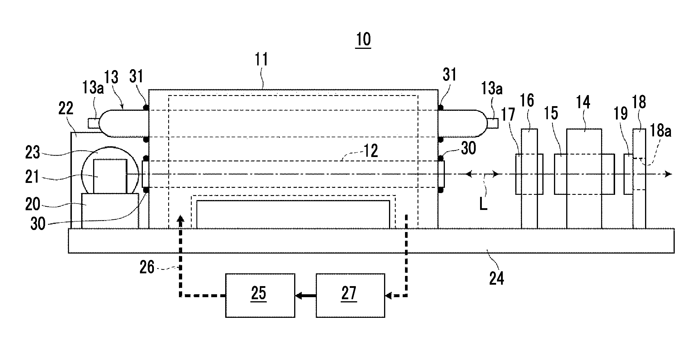
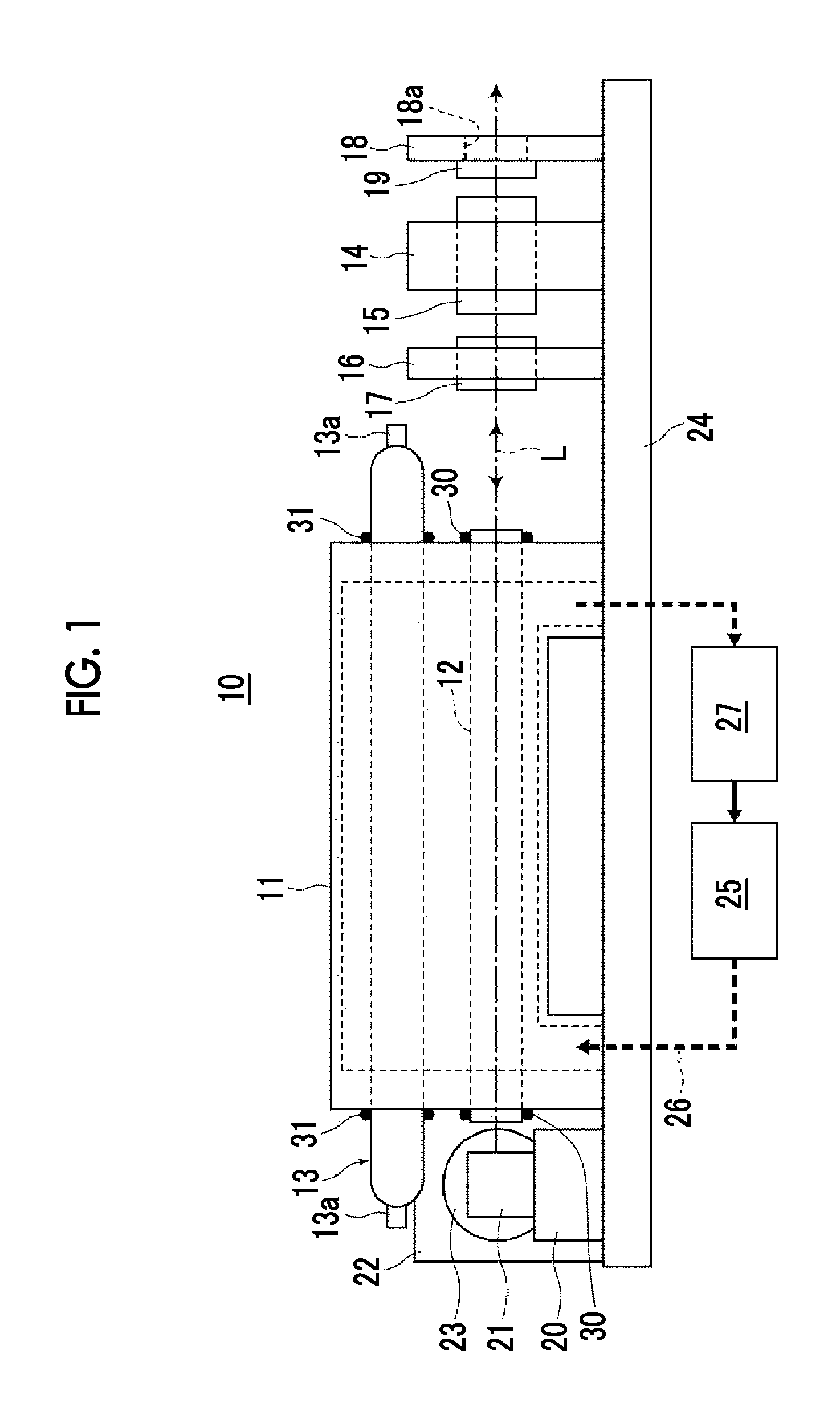
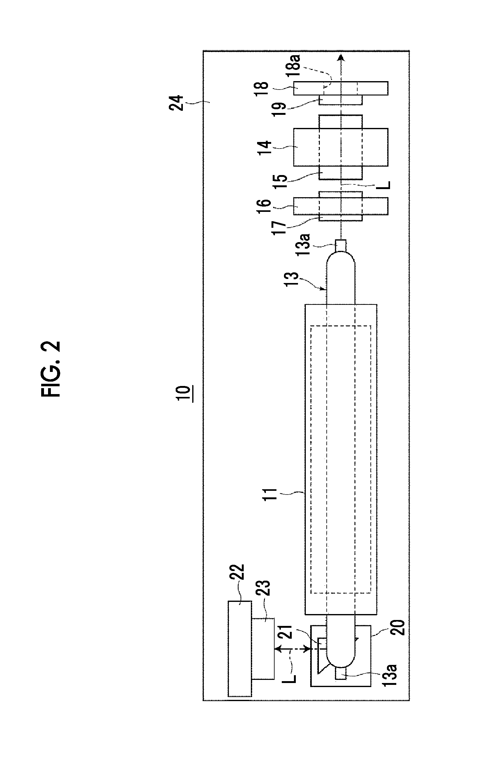
[0058]Hereinafter, an embodiment of the invention will be described in detail referring to the drawings. FIGS. 1 and 2 respectively show a side surface shape and a planar shape of a solid-state laser device 10 according to the invention. In the following description, in FIGS. 1 and 2, the right side in the drawing on which a laser beam to be used is extracted is referred to as a front side or forward, and the left side in the drawing is referred to as a rear side or rearward.

[0059]The solid-state laser device 10 has a laser chamber 11 which has an appearance in a substantially rectangular parallelepiped shape, a solid-state laser medium 12, a part of which is accommodated inside the laser chamber 11, a flash lamp 13 which has a rod-shaped portion extending linearly, a part of the rod-shaped portion being provided inside the laser chamber 11, a Q switching element 15 which is attached to a holder 14, polarizer 17 which is attached to a holder 16 and is disposed between the flash lamp...

second embodiment

[0080]Next, the invention will be described referring to FIG. 5. In FIG. 5, the same components as the components in FIGS. 1 to 4 are represented by the same reference numerals, and description thereof will not be repeated unless particularly necessary (the same applies hereinafter).

[0081]A solid-state laser device 50 of the second embodiment is configured such that the flash lamp 13 is pulled out of the laser chamber 11 forward, that is, rightward in the drawing. That is, in this device, the resonator mirror 23 as a rear mirror is disposed in a state of facing the rear end surface of the solid-state laser medium 12 (see FIG. 1) (not shown) held in the laser chamber 11, and the prism 21 is disposed in a state of facing the front end surface of the solid-state laser medium 12. The prism 21 bends light L emitted from the front end surface of the solid-state laser medium 12 in a direction perpendicular to the optical axis of the solid-state laser medium 12.

[0082]In the solid-state lase...

sixth embodiment

[0096]It is preferable that the light guide member 37 has an antireflection film (AR coat) which is formed on both end surfaces. Alternatively, it is preferable that the light guide member 37 is disposed to be bonded to the solid-state laser medium 12 or the prism 21 through optical contact without using an adhesive. The width or the diameter of the light guide member 37 may be greater than the solid-state laser medium 12. However, the width or diameter of the light guide member 37 is of a size not to interfere with the flash lamp 13 for pulling the flash lamp 13 out rearward. The material for the light guide member 37 is, for example, a light transmissive material, such as quartz glass or acryl. Though not specified in FIG. 13, a light guide member may be provided in the whole or a part between the solid-state laser medium 12 and the polarizer 17. In a case where the optical element which bends the optical path is a mirror or a Brewster polarizer, it is possible to bring the end su...


PUM


Abstract

Disclosed are a solid-state laser device having an advantage of achieving simplification of a configuration and reduction in size, and a photoacoustic measurement device. In a solid-state laser device which accommodates a solid-state laser medium and an excitation light source having a rod-shaped portion, the excitation light source is provided to be pulled out of a laser chamber. An optical element which bends light is provided at a position separated from the rod-shaped portion such that at least a part of the optical element and at least a part of the rod-shaped portion are at the same position in the longitudinal direction of the rod-shaped portion. One resonator mirror is disposed at a position where bent light is incident. Optical components between the optical element and the resonator mirror are provided at positions separated from a path along which the excitation light source is pulled out.

Description

CROSS-REFERENCE TO RELATED APPLICATIONS[0001]This application is a Continuation of PCT International Application No. PCT / JP2014 / 068059 filed on Jul. 7, 2014, which claims priority under 35 U.S.C §119(a) to Japanese Patent Application No. 2013-193199 filed on Sep. 18, 2013 and Japanese Patent Application No. 2014-131451 filed on Jun. 26, 2014. Each of the above application(s) is hereby expressly incorporated by reference, in its entirety, into the present application.BACKGROUND OF THE INVENTION[0002]1. Field of the Invention[0003]The present invention relates to a solid-state laser device, and in particular, to a solid-state laser device in which an excitation light source and a solid-state laser medium are accommodated inside a laser chamber.[0004]The present invention also relates to a photoacoustic measurement device using such a solid-state laser device.[0005]2. Description of the Related Art[0006]Hitherto, as one image inspection method which can noninvasively inspect a state in...

Claims


Application Information

Patent Timeline
IPC IPC(8): H01S3/02H01S3/042G01N21/17H01S3/092
CPCH01S3/025G01N21/1702H01S3/042H01S3/092G01N2201/06113H01S3/0815H01S3/0931H01S3/115
Inventor NAKABAYASHI, KOKITADA, TAKUJI
Owner FUJIFILM CORP
Why Eureka
Try Eureka