Electrically conductive textile assemblies and manufacture thereof

a technology of electrically conductive textiles and textiles, applied in the field of electrically conductive textile assemblies, can solve the problems of reducing conductivity, printing methods are generally unsuitable for products, and the application of relatively complex patterns of electrical paths on the substrate, so as to reduce the intrusion of wearers, reduce the cost, and be more durable under washing

Inactive Publication Date: 2016-07-07
MAS INNOVATION
View PDF0 Cites 26 Cited by
  • Summary
  • Abstract
  • Description
  • Claims
  • Application Information

AI Technical Summary

Benefits of technology

[0126]Advantageously, the use of conductive and thermo-fusible threads on opposite sides of the textile substrate allows the conductive thread to be temporarily anchored to the substrate until the insulating layer can be applied to fix it in place. The thermo-fusible thread can then be removed such that the second surface of the substrate remains substantially free of undesirable visual or haptic features which would otherwise be the case if a normal thread was used in the stitching process. Assemblies produced by the inventive method may comprise conductive paths which are less intrusive to a wearer, as well as more durable under washing. Further, the method may be implemented using conventional sewing or embroidery machinery.
[0127]The method according to aspects and embodiments of the invention mentioned herein enables multiple conductive pathways to be applied to a substrate simultaneously with no short circuiting. Advantageously, conventional embroidery machines or sewing machines can be used, hence reducing the cost and increasing the accuracy of application of the conductive paths. Discrete conductive paths having high degree of complexity of path design may be applied. This is impossible with alternative methods such as knitting or weaving. Additionally, it is possible to apply conductive paths in a manner such that the circuits can accommodate high levels of stretch in one or more desired directions, with no (or at least very insignificant—less than 1%) changes in conductivity, and to achieve high path density (number of paths per unit width).

Problems solved by technology

Since printing methods may employ screens or templates, not only can products in which conductive paths appear on only one side of the textile substrate be made, but it is also possible to apply relatively complex patterns of conductive paths on the substrate.
However, in most instances the applied conductive paths cannot stretch with the substrate without cracking, and printing methods are thus generally unsuitable for products where stretchability is important.
A problem with these inks is that the conductivity decreases when the printed conduction paths are stretched.
This makes them unsuitable for applications such as analog signal transfer, where constant conductivity during stretch is essential.
In general these techniques have the same disadvantages as printing-based methods, in that the conductive material may break (thereby interrupting the conduction path) or the conductivity may change when the substrate is stretched.
Presently known methods of achieving stretchable conductive paths on garments have many flaws, in particular being susceptible to reduced conductivity (which is difficult to predict as it is a nonlinear effect).
Weaving or knitting therefore, in general, cannot create non-linear and complex patterns for the conduction path, and cannot accommodate significant levels of stretching of the substrate, so may be of limited use for advanced wearable electronic apparel applications.
Although woven and knitted fabrics can be cut to the shape of the desired conductive paths for use as an appliqué on a substrate, their use is generally limited to applications where only a few conductive paths are required and a low level of stretch is permitted.
In addition, cutting and re-application of the cut conductive paths onto the substrate is a manual and cumbersome process, and leads to the wastage of costly conductive materials.
As such, a disadvantage of embroidered circuitry is that the embroidery undesirably changes the appearance and tactility of both surfaces of the garment.
To overcome this, it is necessary to use masking in the form of an additional substrate applied to the non-conductive thread, producing a multilayer composite which is heavy and bulky and thus unsuitable for applications such as sportswear, or apparel requiring high flexibility and stretchability and adaptation to body contours during use.
Further, additional process steps are required, increasing the cost of manufacture.

Method used


Image

  • Electrically conductive textile assemblies and manufacture thereof
  • Electrically conductive textile assemblies and manufacture thereof
  • Electrically conductive textile assemblies and manufacture thereof

Examples


Embodiment Construction

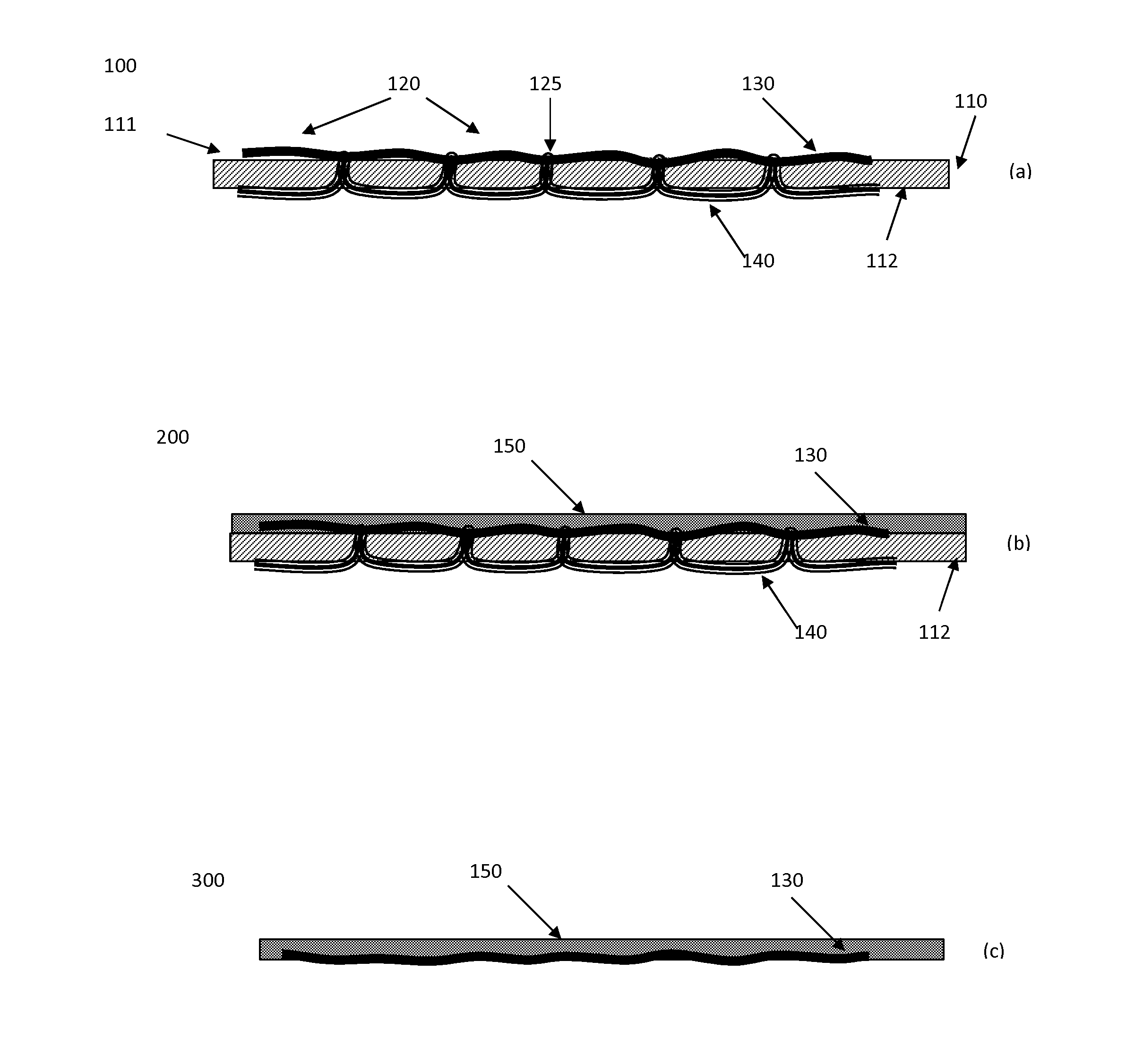
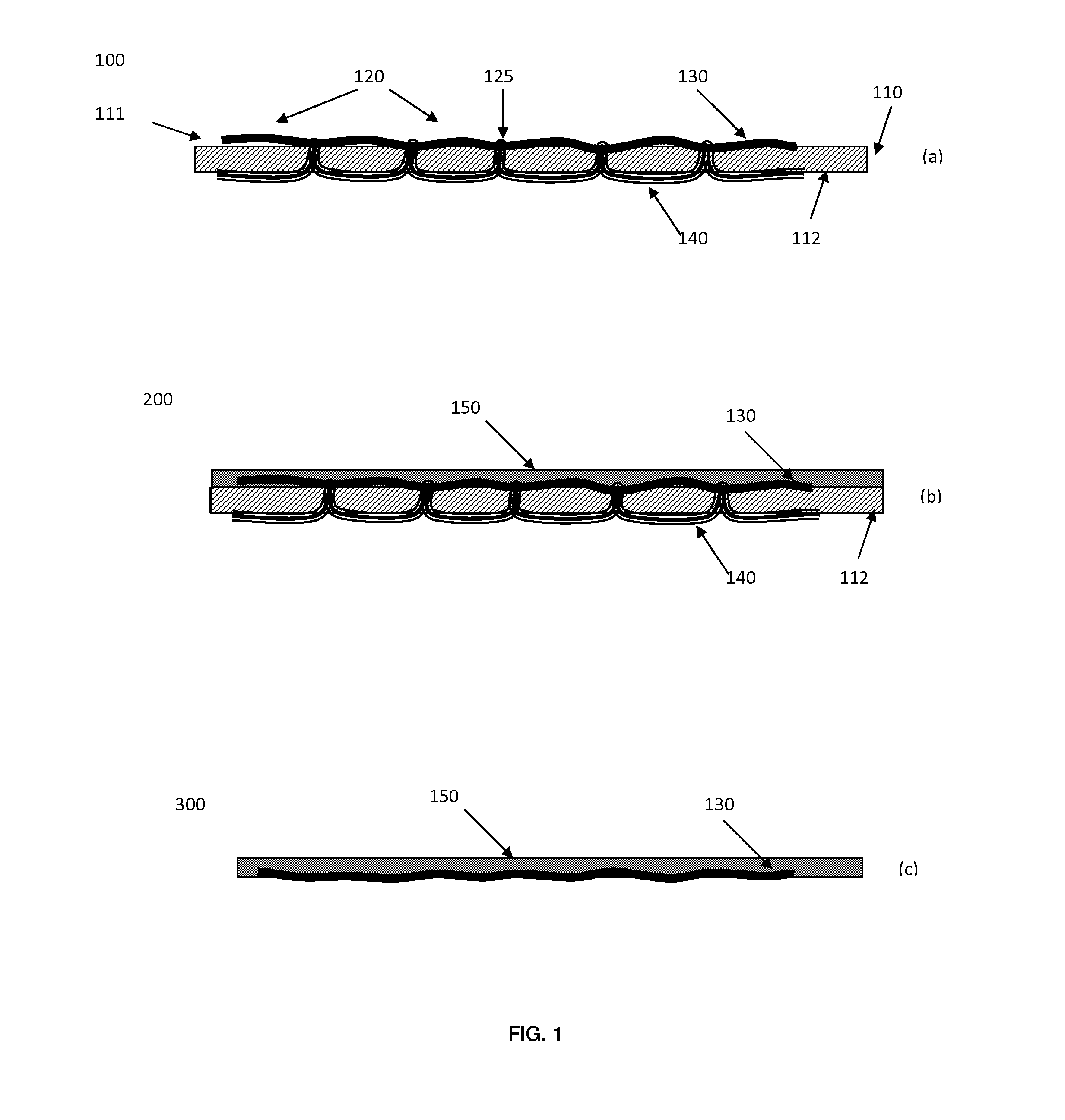
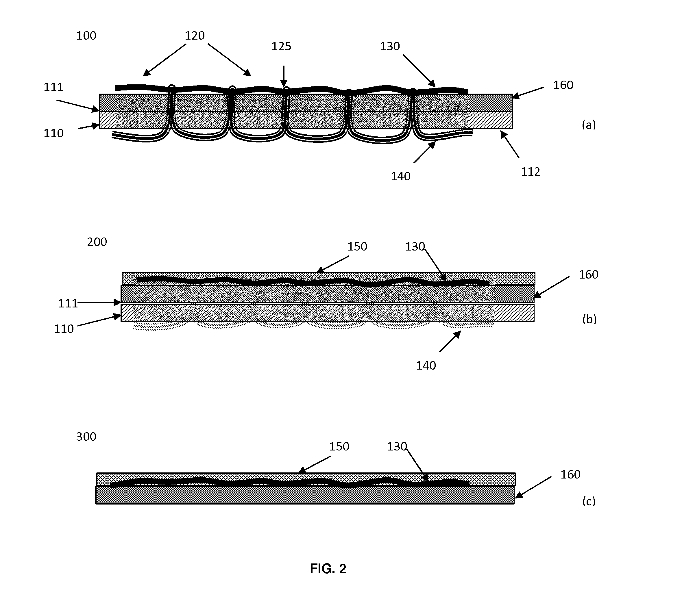
[0199]Certain embodiments of the present invention provide means of creating conductive paths suitable for affixing to stretchable textile substrates. Further embodiments of the present invention provide means of creating conductive paths on stretchable textile substrates. These embodiments addressing one or more of the disadvantages and limitations of prior art methods discussed above.

[0200]Embodiments of the invention relate to the making of conductive paths that may be affixed to textiles or apparel. Additional embodiments of the invention relate to making a conductive path on textiles or apparel. The conductive paths described herein enable textiles or apparel to be used for smart clothing for various applications including sports, well-being, illumination, heating, communication, healthcare monitoring etc. In certain embodiments, an intermediate product may be manufactured that affixes a conductive thread, laid down using a conventional embroidery machinery or a conventional se...


PUM


Abstract

There is provided a method of making a conductive assembly for use in textiles, the method comprising providing a composite material comprising: a temporary substrate having a first surface and a second surface opposite the first surface; a stitching pattern comprising a plurality of lockstitches on the temporary substrate, such that a conductive thread is disposed at the first surface of the temporary substrate and a thermo-fusible thread is disposed at the second surface; and an insulating layer comprising an adhesive on top of at least part of the conductive thread on the first surface, the adhesive having an activation temperature which is higher than the Vicat softening point, as measured by method A120 of ASTM D1525, of the thermo-fusible thread; and heating the insulating layer and thermo-fusible thread to the activation temperature and curing the adhesive in the insulating layer of the composite material, thereby securing the conductive thread to the insulating layer. Articles according to the process are also provided.

Description

BACKGROUND[0001]In the field of e-textiles, one application of which is wearable electronics, electrical and electronic circuitry can be created in or on textiles and apparel by several different methods.[0002]For example, conductive paths may be printed on textile substrates, using screen printing or template printing. Here the screen or the template will be made with open areas for the required conductive regions. The screen or template is placed precisely on the substrate at the desired position for the conductive circuit traces. The print paste or ink used in these methods generally consists of a conductive powder of suitable particle size such as silver, copper, or carbon, and a binder such as acrylic, epoxy, or silicone. The paste or ink is applied on to the textile substrate by the appropriate printing method and is cured under suitable curing conditions to produce a conductive textile product.[0003]The conductivity of the conductive path depends on the width and thickness of...

Claims


Application Information

Patent Timeline
Patent Type & Authority Applications(United States)
IPC IPC(8): D04B1/10
CPCD04B1/102H05K1/0283H05K1/038H05K3/007H05K3/386H05K2203/0156
Inventor SATHARASINGHE, ACHALA SAJEEVAJAYASUNDARA, HASITHAVITARANA, RANIL KIRTHI
Owner MAS INNOVATION
Why Eureka
Try Eureka