Radio frequency circuit structure for implementing function of converting GNSS satellite signal into baseband signal

a radio frequency circuit and satellite signal technology, applied in satellite radio beaconing, measurement devices, instruments, etc., can solve the problems of high processing speed of baseband circuits, difficult implementation and extremely costly, significant increase of cost, power consumption and size of the overall system, etc., to ensure signal quality, reduce complexity, and low crosstalk

Active Publication Date: 2016-07-07
COMNAV TECH
View PDF3 Cites 9 Cited by
  • Summary
  • Abstract
  • Description
  • Claims
  • Application Information

AI Technical Summary

Benefits of technology

[0006]The object of this invention is to overcome the disadvantages of the prior arts by providing RF circuit structure for implementing the function of converting GNSS satellite signal to baseband signal, which is with the advantage of reduced complexity, low crosstalk between the various satellite signals, ensured signal quality, sufficient signal-to-noise ratio (SNR) for baseband processing circuit and a wide applications area.
[0025]For this invention, the RF circuit structure for implementing the function of converting GNSS satellite signal into a baseband signal has the following beneficial effects:
[0026]1. By using the near zero-IF design, only one level of frequency converting is needed for converting multi-mode multi-band GNSS satellite signal from 1.15˜1.65 GHz frequency band directly to the vicinity of zero-frequency, which greatly reduces the complexity of the system, reduces the cost, power and volume of the system, and avoids the problem of DC offset in the zero-IF design.
[0027]2. By using the high-performance image rejection mixer, the mirrored interference suppression is greater than 20 dB, which ensures the signal quality. By using the high isolation mixers and power dividers, power level of LO leakage signal transferred to the antenna RF port is less than −102 dBm.
[0028]3. GNSS satellite signal in each frequency band is frequency converted and subsequently signal processed, which can reduce crosstalk between the various satellite signals, ensure signal quality and provide adequate SNR for the baseband processing circuit and be with a wider application areas.

Problems solved by technology

Theoretically the desired multi-mode multi-frequency GNSS satellite signals in the L band can be filtered out and then amplified for digital sampling, but this requires a more than 1 GHz of sampling frequency of audio-to-digital (A / D) convertor and high processing speed of baseband circuit, which is difficult to implement and extremely costly in the current technical conditions.
Since this design has a very complex circuit structure, when the processing up to eight bands of multi-mode multi-band GNSS satellite signal, a large number of local oscillation (LO) circuits and mixer circuits must be accompanied.
This may cause great difficulties to debug the system and lead to a significant increase of cost, power consumption and size for the overall system, which can't meet the requirement of portable applications with GNSS receiver.
The circuit structure of this design is simpler than the former one, but there is the problem of direct current (DC) offset signal, which causes great difficulties to subsequent baseband processing.

Method used


Image

  • Radio frequency circuit structure for implementing function of converting GNSS satellite signal into baseband signal
  • Radio frequency circuit structure for implementing function of converting GNSS satellite signal into baseband signal
  • Radio frequency circuit structure for implementing function of converting GNSS satellite signal into baseband signal

Examples


Embodiment Construction

[0032]In order to clearly illustrate the technical content of this invention, the embodiment below is for further describing.

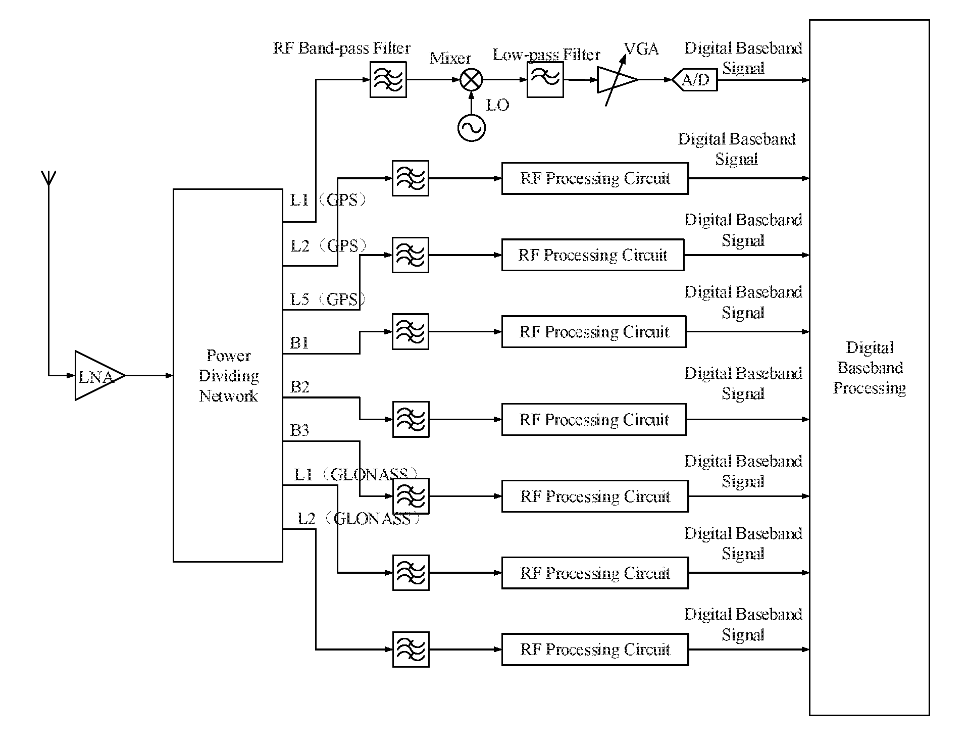
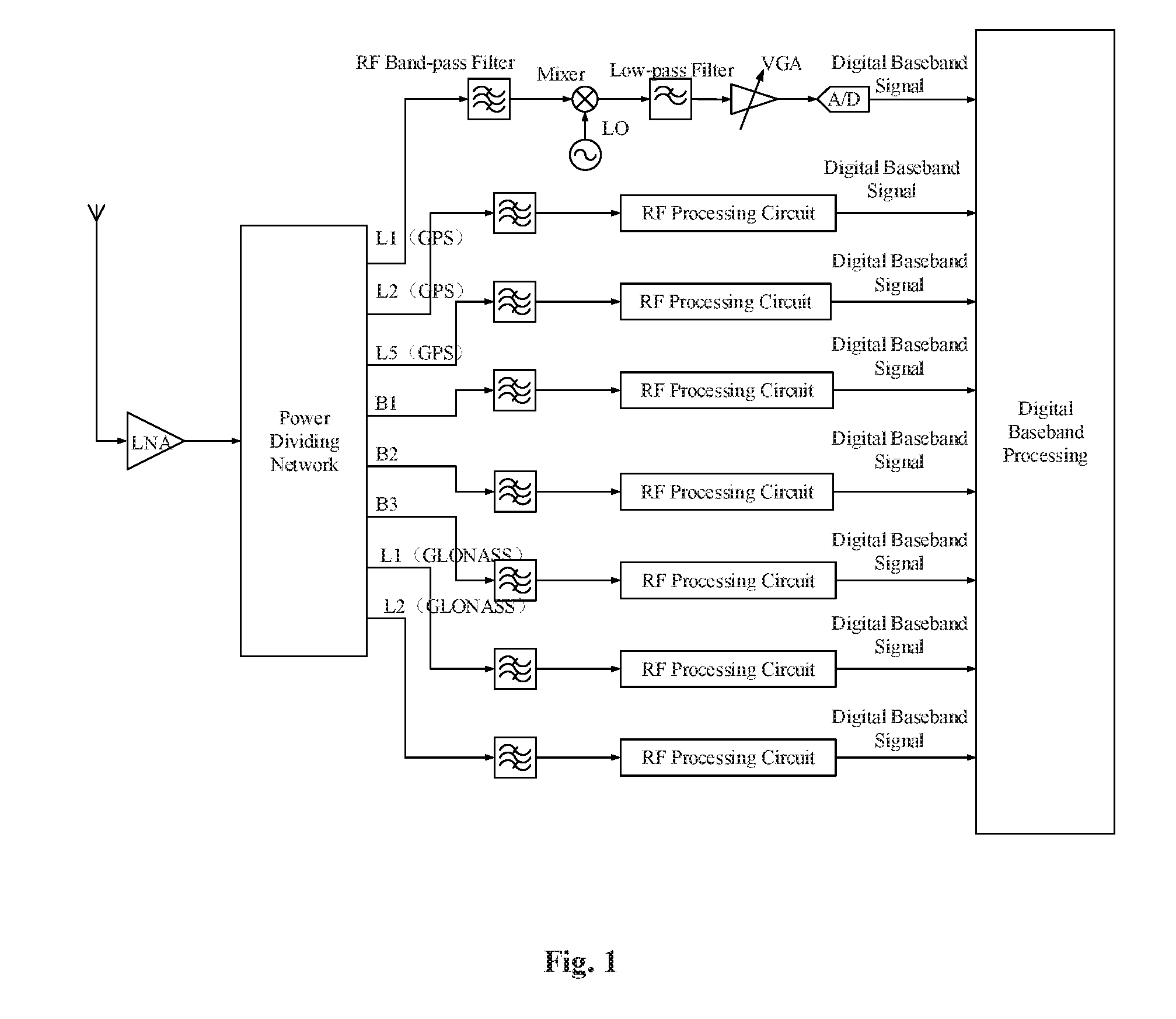
[0033]FIG. 1 is an overall block diagram of this invention, which is the RF circuit structure for implementing the function of converting GNSS satellite signal into baseband signal.

[0034]The circuit structure for implementing the function of converting GNSS satellite signal into baseband signal comprises:

[0035](1) a channel dividing module, for dividing GNSS satellite signals into a number of different channels of satellite signals according to the carrier frequency;

[0036]wherein the channel dividing module divides GNSS satellite signal into GPS L1 / L2 / L5 signal, Beidou II B1 / B2 / B3 signal and GLONASS L1 / L2 signal.

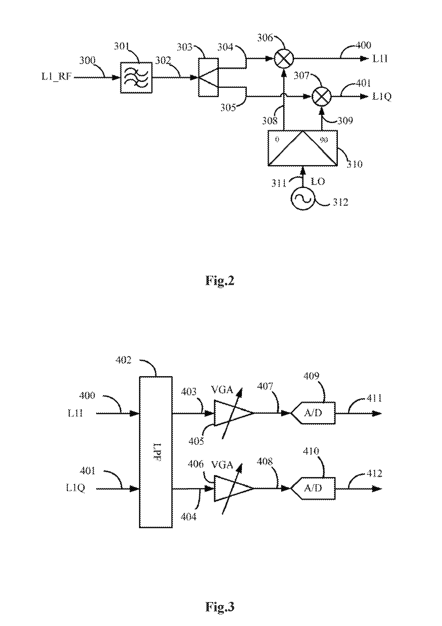
[0037](2) a plurality of frequency converting modules, each of which is corresponding to each channel output from the channel dividing module and each of which is used for converting each signal in corresponding output channel of the channel dividing m...


PUM


Abstract

The present invention relates to a radio frequency circuit structure for implementing a function of converting a satellite signal of a global navigation satellite system into a baseband signal. The radio frequency circuit structure comprises a channel dividing function module, a plurality of frequency converting function modules, a plurality of local oscillator signal modules, and a plurality of analog-to-digital convertor modules. The channel dividing function module is used for dividing a satellite signal of the global navigation satellite system received by an antenna into satellite signals in a plurality of channels. Each of the frequency converting function modules is used for performing frequency conversion on the satellite signals in the corresponding channels to form near zero-frequency signals. Each of the local oscillator signal module is used for generating a local oscillator signal and outputting the local oscillator signal to the frequency converting function module. By using the radio frequency circuit structure for implementing a function of converting a satellite signal of a global navigation satellite system into a baseband signal, frequency conversion and follow-up signal processing can be performed on the satellite signals in each frequency band separately, the signal quality insured, a sufficient signal to noise ratio is provided for a baseband processing circuit, thereby providing a wider application range.

Description

FIELD OF TECHNOLOGY[0001]This invention relates to the field of global navigation satellite systems (GNSS), more particularly to the field of radio frequency (RF) circuit in GNSS receiver, specifically refers to an RF circuit structure for implementing function of converting GNSS satellite signal into baseband signal.DESCRIPTION OF RELATED ARTS[0002]Beidou satellite navigation system (especially the second-generation Beidou satellite navigation system), GPS (Global Positioning System), GLONASS (GLONASS is the acronym of Global Navigation Satellite System in Russian) and Galileo (Galileo is the European satellite navigation System) are global satellite navigation and positioning systems respectively established by China, the United States, Russia and EU.[0003]The current mainstream navigation method is that the navigation data are transmitted to the receiver for determining the satellite's position when transmitting signals and a ranging code allows the users' receiver to determine t...

Claims


Application Information

Patent Timeline
Patent Type & Authority Applications(United States)
IPC IPC(8): G01S19/36G01S19/33
CPCG01S19/33G01S19/36G01S19/32G01S19/35G01S19/37
Inventor LIU, JIEWANG, YONGQUANSONG, YANG
Owner COMNAV TECH
Why Eureka
Try Eureka