Dual mode cmut transducer

a transducer and dual-mode technology, applied in the field of ultrasonic diagnostic imaging systems with cmut transducer probes, can solve the problems of lower yields of transducer stack units, increased manufacturing complexity of final transducer probes, and reduced cost of system mainframes, so as to achieve the effect of improving the sensitivity of cmut transducers

Inactive Publication Date: 2016-07-14
KONINKLJIJKE PHILIPS NV
View PDF7 Cites 22 Cited by
  • Summary
  • Abstract
  • Description
  • Claims
  • Application Information

AI Technical Summary

Benefits of technology

[0011]It is an object of the present invention to provide an ultrasonic imaging system of the kind set forth in the opening paragraph which provides an improved sensitivity of the CMUT transducer over a broad range of frequencies used in ultrasonic imaging.

Problems solved by technology

However the ceramic PZT materials require manufacturing processes including dicing, matching layer bonding, fillers, electroplating and interconnections that are distinctly different and complex and require extensive handling, all of which can result in transducer stack unit yields that are lower than desired.
Furthermore, this manufacturing complexity increases the cost of the final transducer probe.
As ultrasound system mainframes have become smaller and dominated by field programmable gate arrays (FPGAs) and software for much of the signal processing functionality, the cost of system mainframes has dropped with the size of the systems.
As a result, the cost of the transducer probe is an ever-increasing percentage of the overall cost of the system, an increase which has been accelerated by the advent of higher element-count arrays used for 3D imaging.
A disadvantage of operating the CMUT in this manner is that if the diaphragm touches the substrate it can become stuck to the floor of the CMUT cell by VanderWaals forces, rendering the CMUT inoperable.
This disadvantage is recognized by Barnes et al., who suggested making the standard accommodation of the bias voltage for the expected vibration of the diaphragm, using a lower bias voltage and greater spacing between the diaphragm and substrate for strong transmission vibration of the diaphragm, and a higher bias voltage and lesser spacing when the small vibrations of echo signals are being received.
Next to the possibility of the diaphragm sticking, another drawback of the operating a conventional CMUT during the reception of an ultrasound signal is that this spring softening effect is negligible in practice, and the resultant sensitivity due to the effect is poor.
The disadvantage of this solution is that the adjustment of the CMUT transceiver gap has to be predefined during the manufacturing (providing either protruding element or a receding element).

Method used


Image

  • Dual mode cmut transducer
  • Dual mode cmut transducer
  • Dual mode cmut transducer

Examples


Embodiment Construction

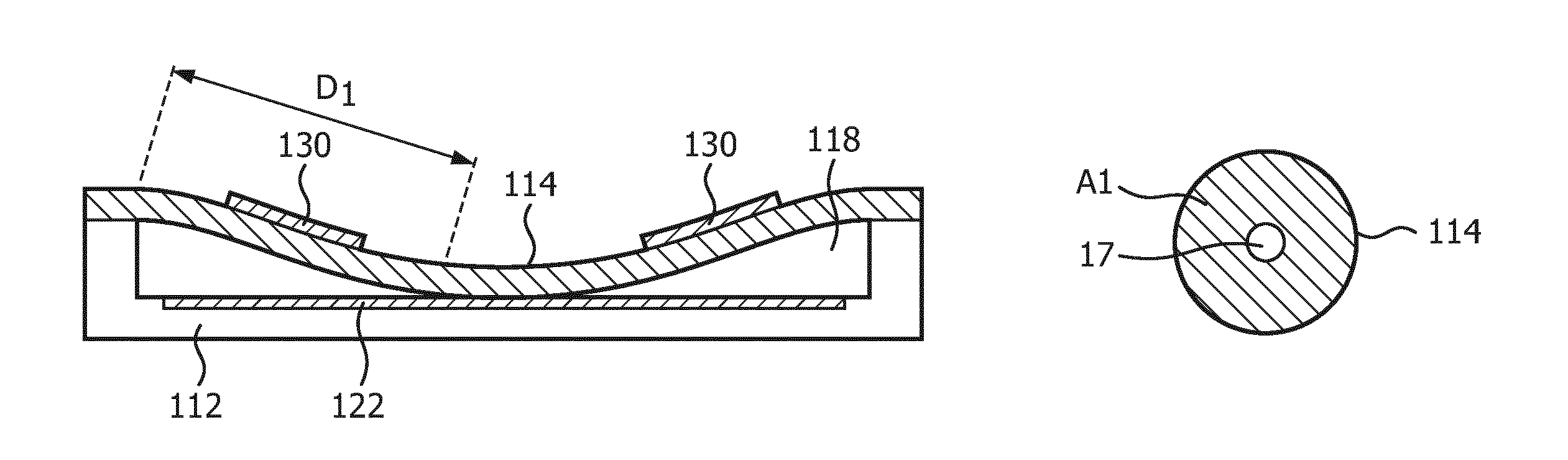
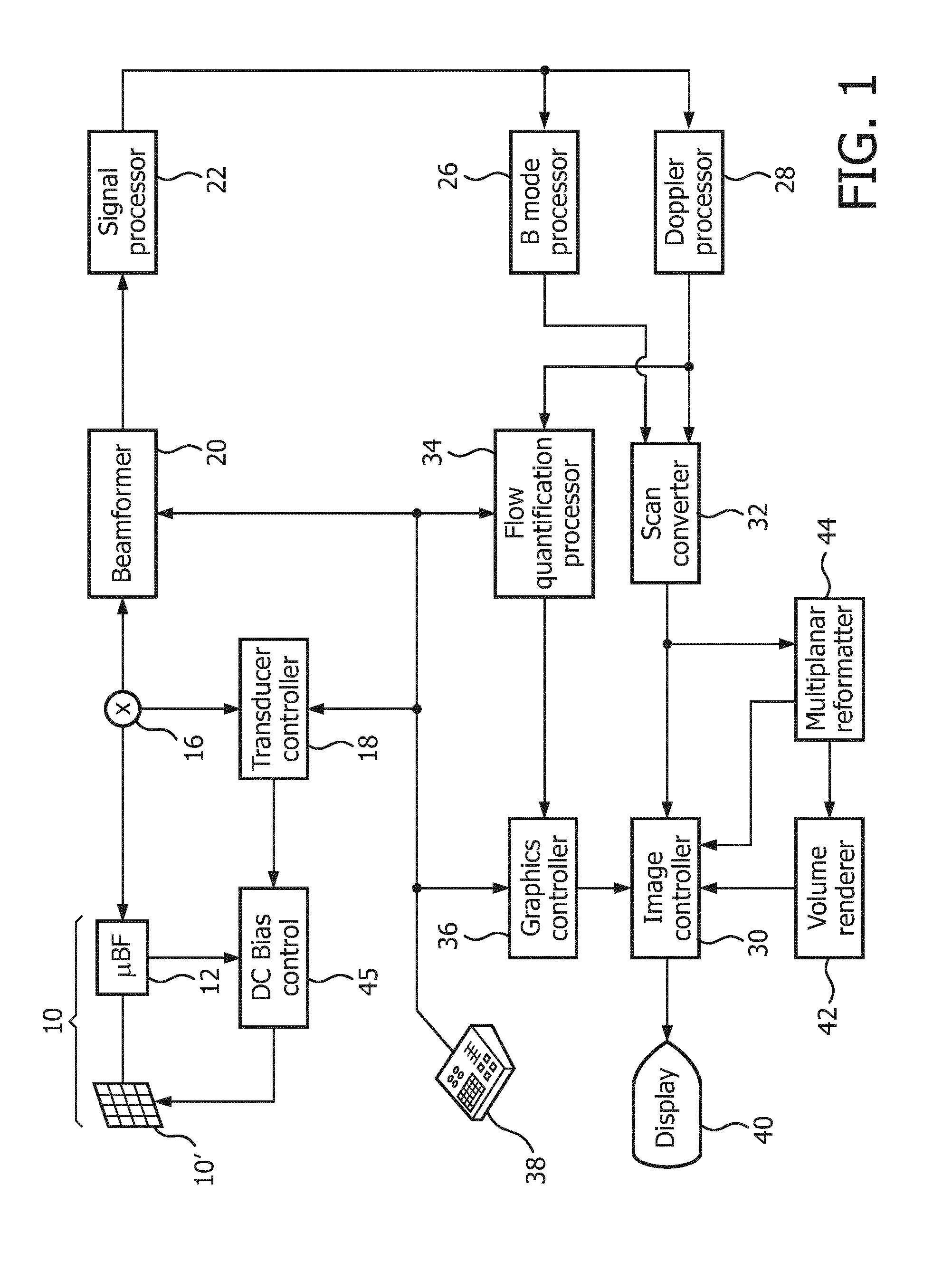
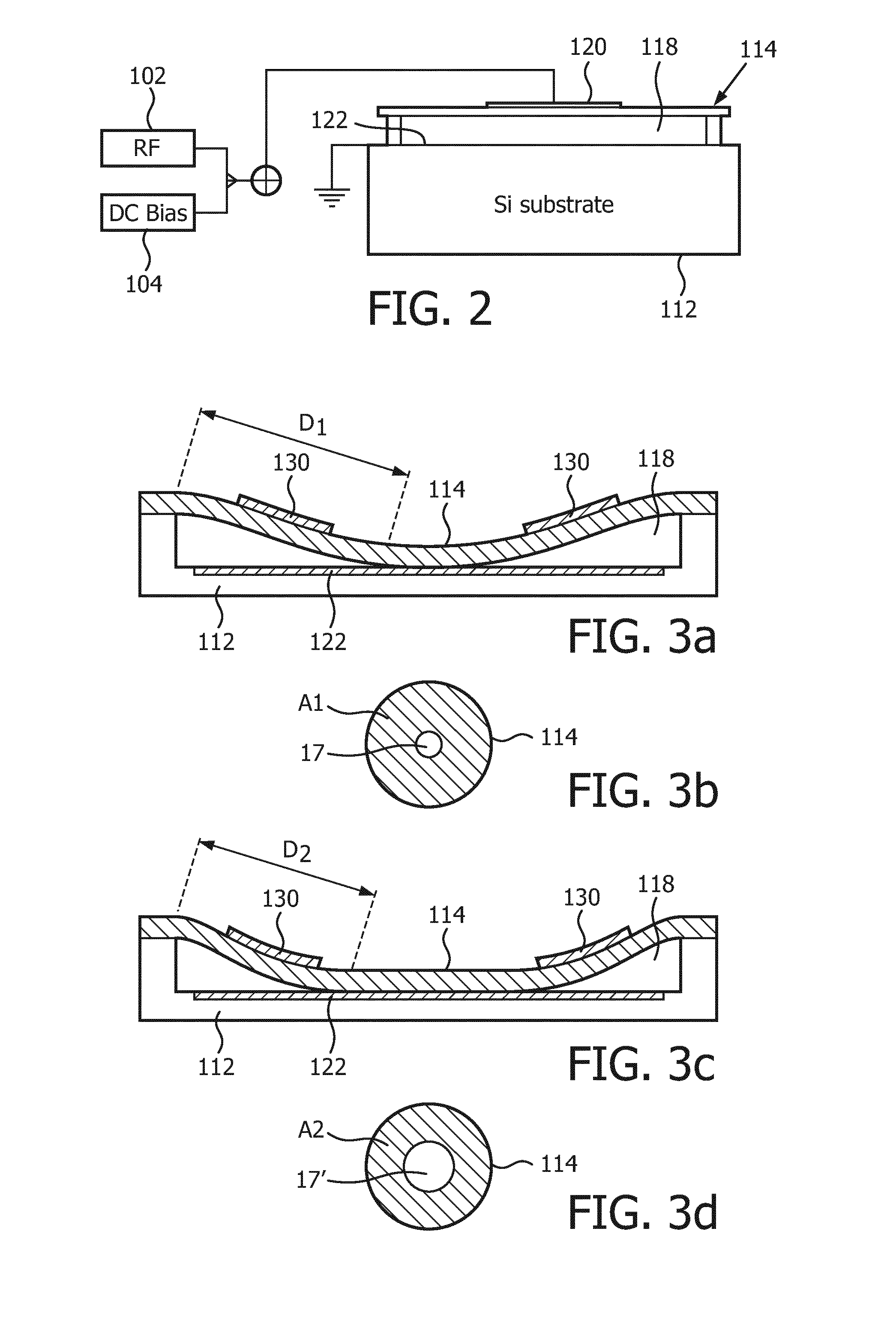
[0053]Referring first to FIG. 1, an ultrasonic diagnostic imaging system with a frequency-controlled CMUT probe is shown in block diagram form. In FIG. 1 a CMUT transducer array 10′ is provided in an ultrasound probe 10 for transmitting ultrasonic waves and receiving echo information. The transducer array 10′ is a one- or a two-dimensional array of transducer elements capable of scanning in a 2D plane or in three dimensions for 3D imaging. The transducer array is coupled to a microbeamformer 12 in the probe which controls transmission and reception of signals by the CMUT array cells. Microbeamformers are capable of at least partial beamforming of the signals received by groups or “patches” of transducer elements as described in U.S. Pat. No. 5,997,479 (Savord et al.), U.S. Pat. No. 6,013,032 (Savord), and U.S. Pat. No. 6,623,432 (Powers et al.) The microbeamformer is coupled by the probe cable to a transmit / receive (T / R) switch 16 which switches between transmission and reception an...


PUM


Abstract

An ultrasonic diagnostic imaging system comprises a CMUT transducer probe with an array (10′) of CMUT cells either of the same or variable diameters operated in a conventional mode during ultrasonic signal reception and a collapsed mode during ultrasonic signal transmission. The frequency response to the CMUT cells is tailored for different clinical applications or continuously varied during echo reception by decreasing the DC bias voltage for the CMUT cells for lower frequency clinical applications, increasing the DC bias voltage for higher frequency clinical applications, or continuously decreasing the DC bias voltage as echoes are received to track the information frequency composition of the returning echo signals.

Description

FIELD OF THE INVENTION[0001]This invention relates to an ultrasonic diagnostic imaging system with a CMUT transducer probe comprising an array comprising one or a plurality of CMUT cells, wherein each CMUT cell has a cell membrane, a membrane electrode, a cell floor, a substrate, and a substrate electrode; and a source of DC bias voltage coupled to the membrane electrode and the substrate electrode. Further this invention relates to a method of operating the ultrasonic diagnostic imaging system.BACKGROUND OF THE INVENTION[0002]The ultrasonic transducers used for medical imaging have numerous characteristics that lead to the production of high quality diagnostic images. Among these are broad bandwidth and high sensitivity to low level acoustic signals at ultrasonic frequencies. Conventionally the piezoelectric materials which possess these characteristics have been made of PZT and PVDF materials, with PZT being the most preferred. However the ceramic PZT materials require manufacturi...

Claims


Application Information

Patent Timeline
Patent Type & Authority Applications(United States)
IPC IPC(8): A61B8/00H02N1/08H02N1/00
CPCA61B8/4494H02N1/08H02N1/006B06B1/02B06B1/0292A61B8/4411A61B8/4438
Inventor PATIL, ABHAY VIJAYSONG, JUNHO
Owner KONINKLJIJKE PHILIPS NV
Why Eureka
Try Eureka