Two-dimensional antenna array, one-dimensional antenna array and single differential feeding antenna

a dual-antenna system, one-dimensional technology, applied in individual energised antenna arrays, substantially flat resonant elements, resonant antennas, etc., can solve the problems of interference of radio signal at the receiving port, more signal leakage, and the isolation mean of the first type is not the best one, so as to enhance the isolation of the dual-antenna system

Inactive Publication Date: 2016-07-14
U&U ENG
View PDF3 Cites 19 Cited by
  • Summary
  • Abstract
  • Description
  • Claims
  • Application Information

AI Technical Summary

Benefits of technology

[0017]The one-dimensional antenna array of the dual-antenna system includes multiple parallel non-high-order-mode differential feeding antennas, so an isolation of the dual-antenna system is enhanced. Furthermore, since the length of the microstrip antenna stripe is no longer than a dielectric wavelength, the one-dimensional antenna array is smaller than the conventional one-dimensional differential leaky-wave antenna array and a beam width is further concentrated at the elevation direction. Since the length of the microstrip antenna stripe is no longer than the dielectric wavelength, so the microstrip antenna stripe is not excited to a high-order mode. Therefore, an angle of inclination of the main beam aligns with the broadside of the non-high-order-mode differential feeding antenna and is perpendicular to a plan of the non-high-order-mode differential feeding antenna.

Problems solved by technology

However, the radio signal at the receiving port is interfered by coupling with the radio signal with enhanced radio signal at the transmitting port.
In addition, an impedance of the antenna does not match that of the circulator, so that a reflection coefficient (S11) of the signal antenna is increased to result in a more signal leakage.
Therefore, the isolation mean of the first type is not the best one and has other design limitation.
However, larger space is also required accordingly.
A manufacturing procedure is more complex and the product uniformity is hardly controlled accordingly.
However, this modified dual-antenna structure has drawbacks of forming the slot which are the same as the second modified dual-antenna structure mentioned above.
However, an accuracy of polarizing antenna is not easy and the isolation is not easily controlled.
In addition, forming the T-shaped slot has the same drawback of the third type.
However, each of the transmitting antenna 61 or the receiving antenna 62 of the leaky-wave dual-antenna system 60 is not further designed as a two-dimensional antenna array since the length thereof is equal or greater than three times of the wavelength and the one-dimensional antenna array has many design limitations.

Method used


Image

  • Two-dimensional antenna array, one-dimensional antenna array and single differential feeding antenna
  • Two-dimensional antenna array, one-dimensional antenna array and single differential feeding antenna
  • Two-dimensional antenna array, one-dimensional antenna array and single differential feeding antenna

Examples


Embodiment Construction

[0033]The present invention provides a two-dimensional antenna array of a dual-antenna system having high isolation and two-dimensional narrow beam, an one-dimensional antenna array of the dual-antenna system and a single differential feeding antenna. Multiple embodiments are further described as follow.

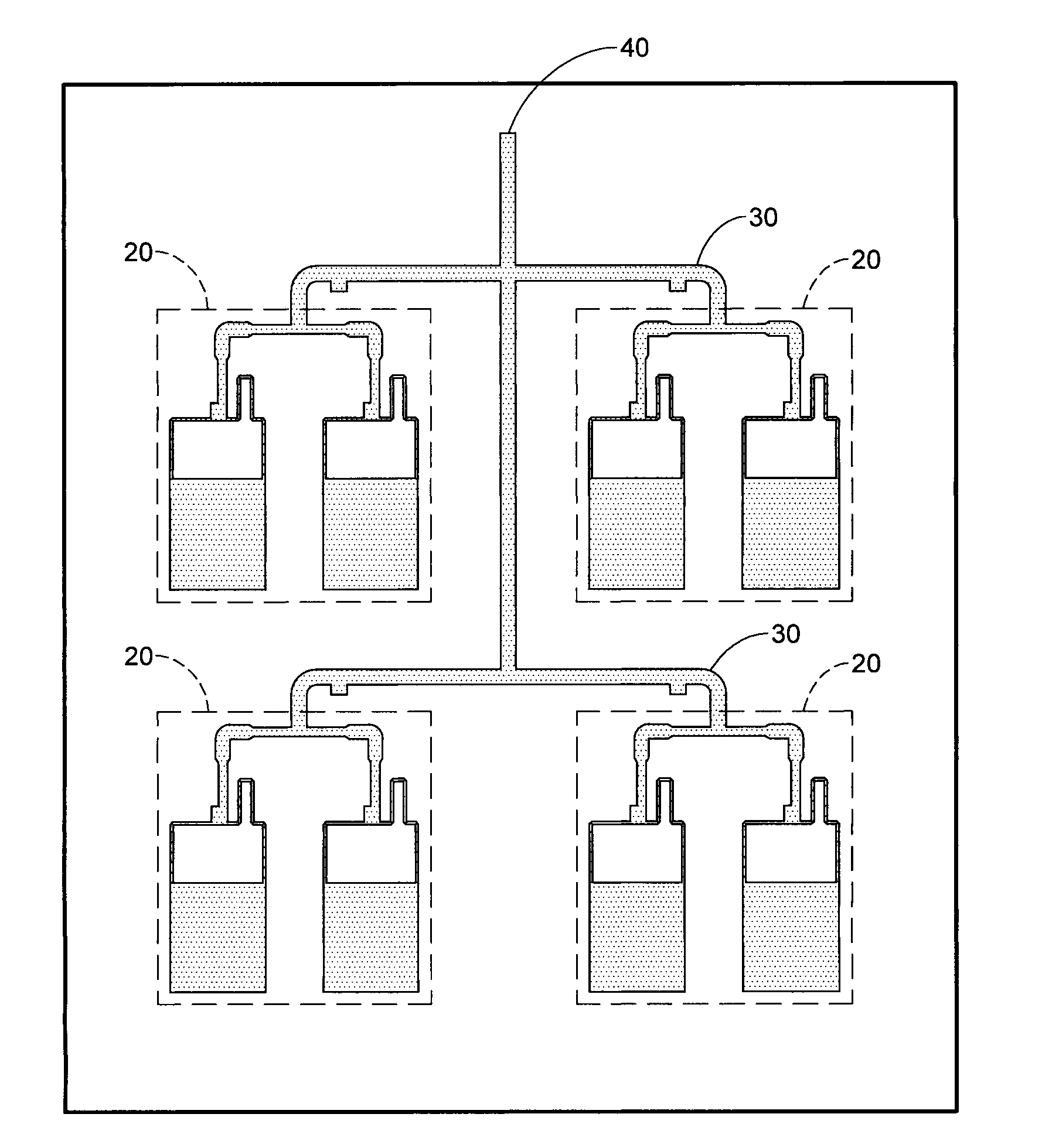
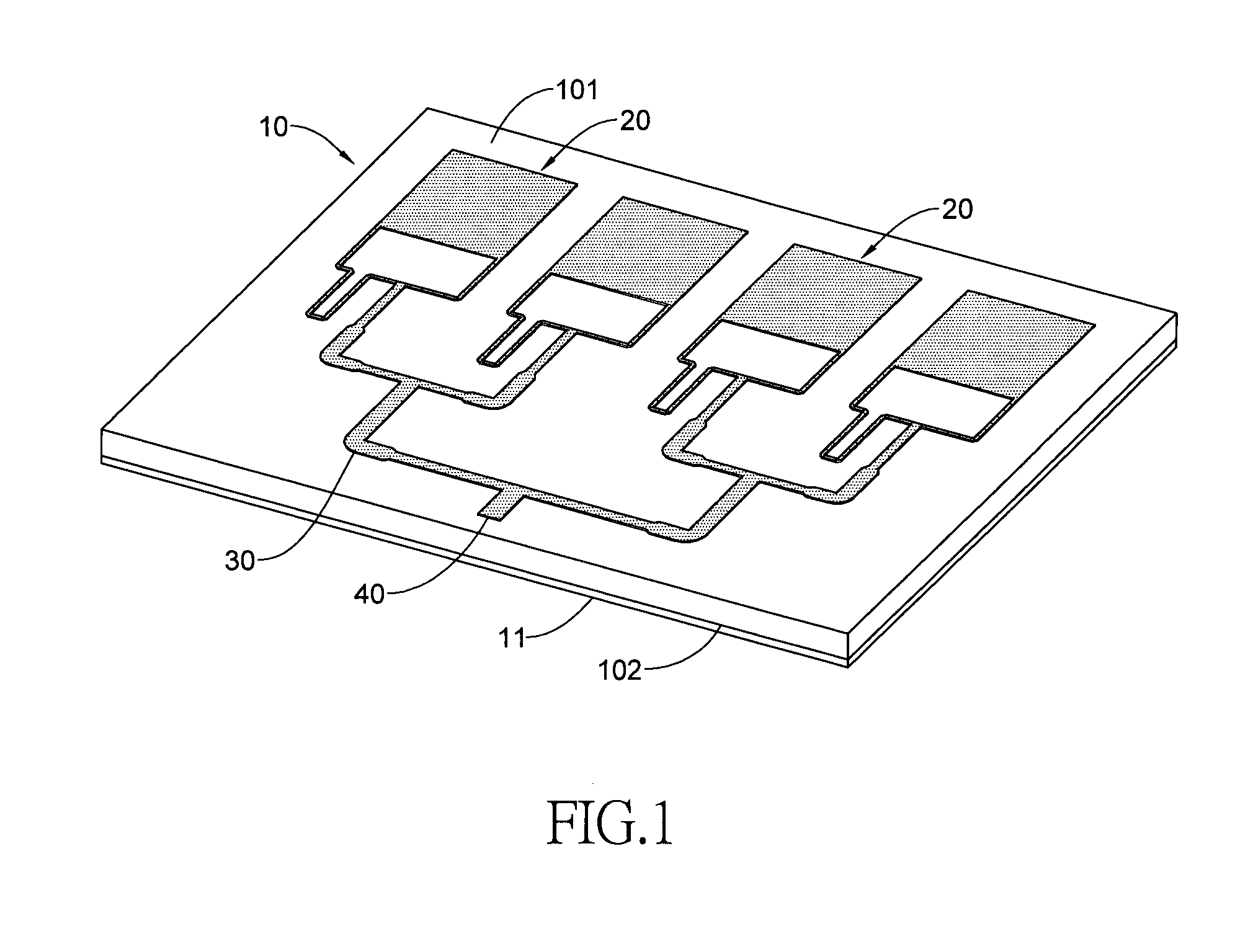
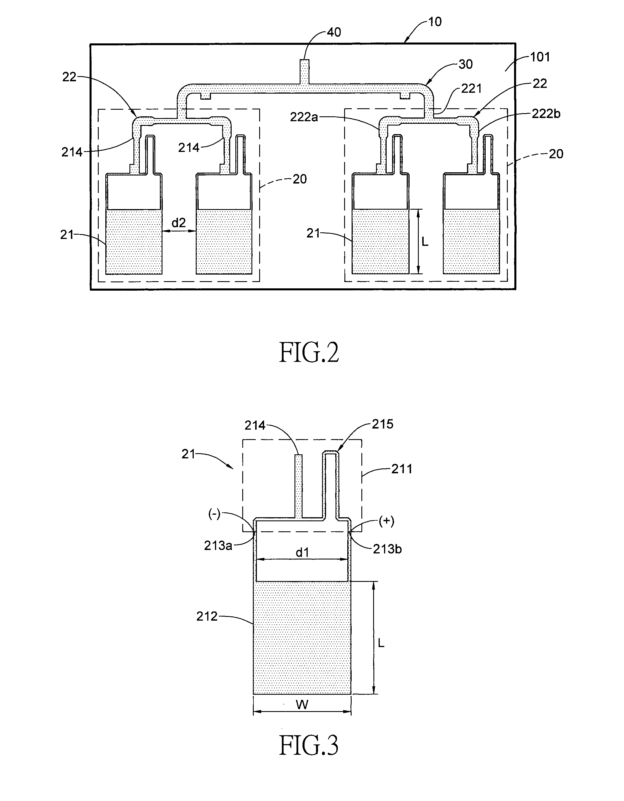
[0034]The dual-antenna system has a transmitting antenna and a receiving antenna. Each of the transmitting and receiving antennas may be the one-dimensional antenna array or the two-dimensional antenna. With reference to FIGS. 1 and 2, a first preferred embodiment of the present invention discloses 1×2 one-dimensional antenna array. The one-dimensional antenna array has a dielectric substrate 10, m antenna units 20 arranged to one row (m=2), a power dividing circuit 30, a main feeding point 40 and a grounding layer 11. The power dividing circuit 30 is connected to the two antenna units 20 and the main feeding point 40 is connected to the power dividing circuit 30.

[0035]The dielectric...


PUM


Abstract

A two-dimensional antenna array has n rows of 1×m one-dimensional array and each one-dimensional array is composed of multiple single differential feeding antennas. Each single differential feeding antenna has a differential feeding structure and a microstrip antenna stripe. A length of the microstrip antenna stripe is no longer than a dielectric wavelength so the microstrip antenna stripe is not excited to a high-order mode. An angle of inclination of a main beam aligns with the broadside and a width of the main beam is further concentrated at elevation direction. The differential feeding structure can reduce an even mode to enhance an isolation. The one and two-dimensional antenna array is miniature by using the small single differential feeding antennas. In addition, the isolation and gain of a dual-antenna system using the two-dimensional antenna arrays or the one-dimensional antenna arrays are further enhanced and increased if more feeding antenna arrays are used.

Description

CROSS-REFERENCE TO RELATED APPLICATIONS[0001]This application is based upon and claims priority under 35 U.S.C. 119 from Taiwan Patent Application No. 104100898 filed on Jan. 12, 2015, which is hereby specifically incorporated herein by this reference thereto.BACKGROUND OF THE INVENTION[0002]1. Field of the Invention[0003]The present invention is related to an antenna array of a dual-antenna system, and more particularly to a two-dimensional antenna array and one-dimensional antenna array of a dual-antenna system having a high isolation.[0004]2. Description of the Prior Arts[0005]Generally, a radar transceiver has a receiving port and a transmitting port to respectively receive and transmit the radio signal. The radio signal can be transmitted to a farther way if an intensity of the radio signal is enhanced at the transmitting port. However, the radio signal at the receiving port is interfered by coupling with the radio signal with enhanced radio signal at the transmitting port. Acc...

Claims


Application Information

Patent Timeline
Patent Type & Authority Applications(United States)
IPC IPC(8): H01Q21/06H01Q9/04H01Q21/00
CPCH01Q21/065H01Q9/045H01Q21/0075H01Q1/523H01Q21/08
Inventor HU, CHUN-HAOCHANG, CHI-HOLIN, YO-SHENGTSAO, PING-CHANG
Owner U&U ENG
Why Eureka
Try Eureka