Ring-modulated laser

a ring-modulated laser and laser technology, applied in lasers, lasers, laser optical resonator construction, etc., can solve the problems of high modulation voltage/power, difficult to achieve precise and dynamic tuning, and long mzi modulator

Active Publication Date: 2016-07-14
ORACLE INT CORP
View PDF5 Cites 27 Cited by
  • Summary
  • Abstract
  • Description
  • Claims
  • Application Information

AI Technical Summary

Benefits of technology

[0011]Moreover, the pair of ring-resonator modulators may electrically modulate optical loss in the optical cavity. Note that the pair of ring-resonator modulators may be push-pull modulated so that in a first state resonances of the pair of ring-resonator modulators are aligned and in a second state the resonances are pushed apart.

Problems solved by technology

This precise and dynamic tuning can be difficult to implement, and often consumes a large amount of electrical power and results in control circuits that occupy large areas on integrated circuits.
Therefore, MZI modulators are usually very long, and need high modulation voltage / power.

Method used


Image

  • Ring-modulated laser
  • Ring-modulated laser
  • Ring-modulated laser

Examples


Embodiment Construction

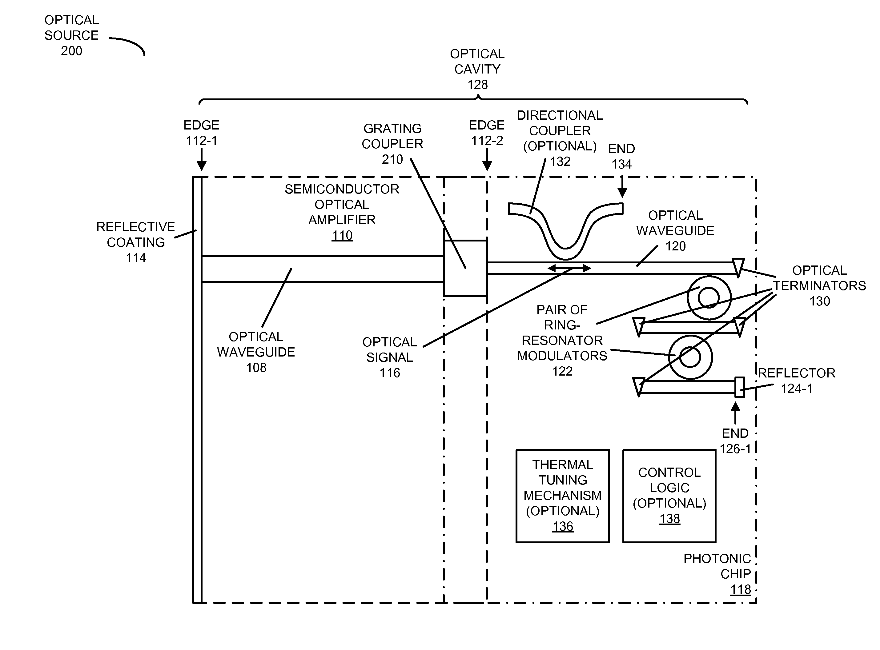
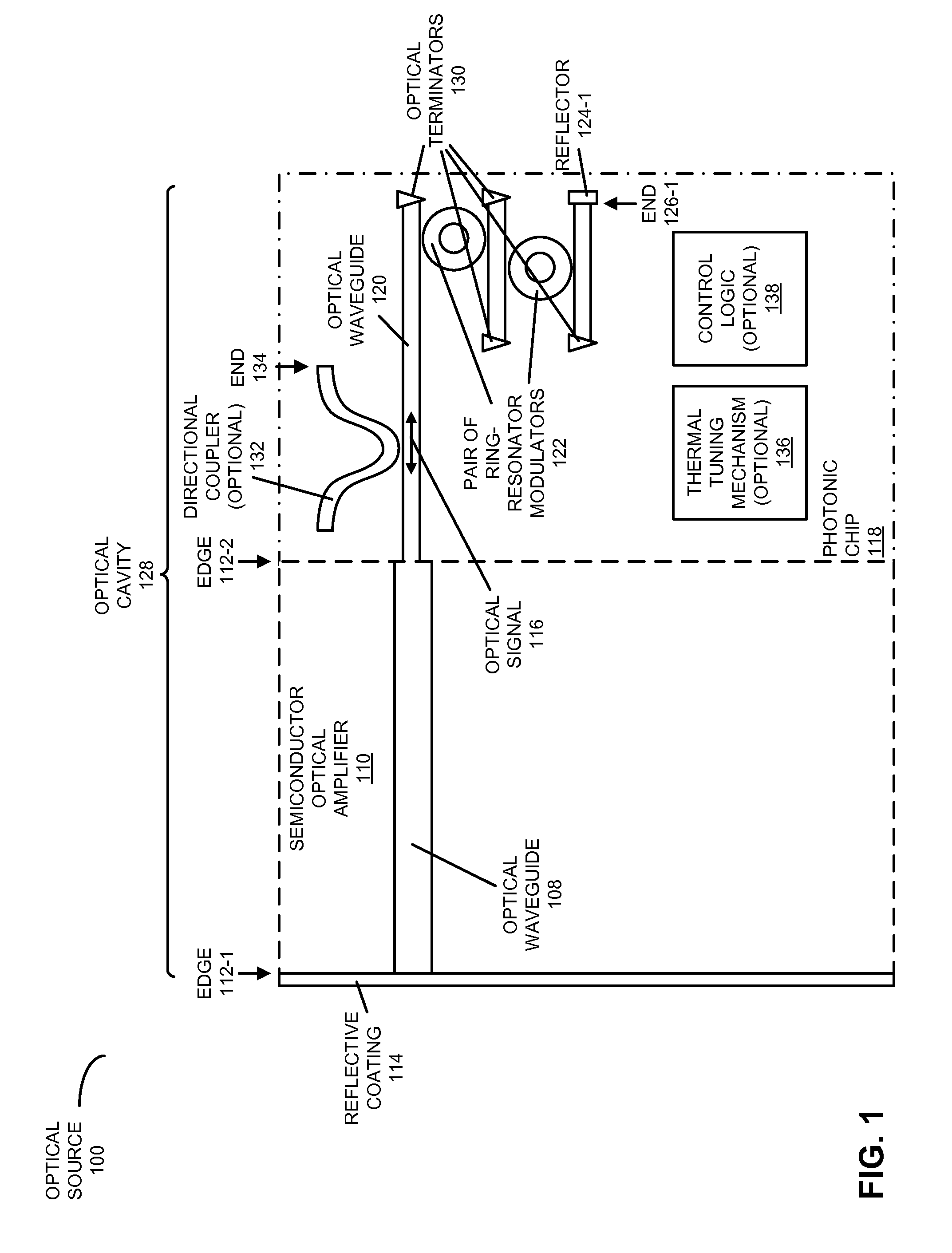
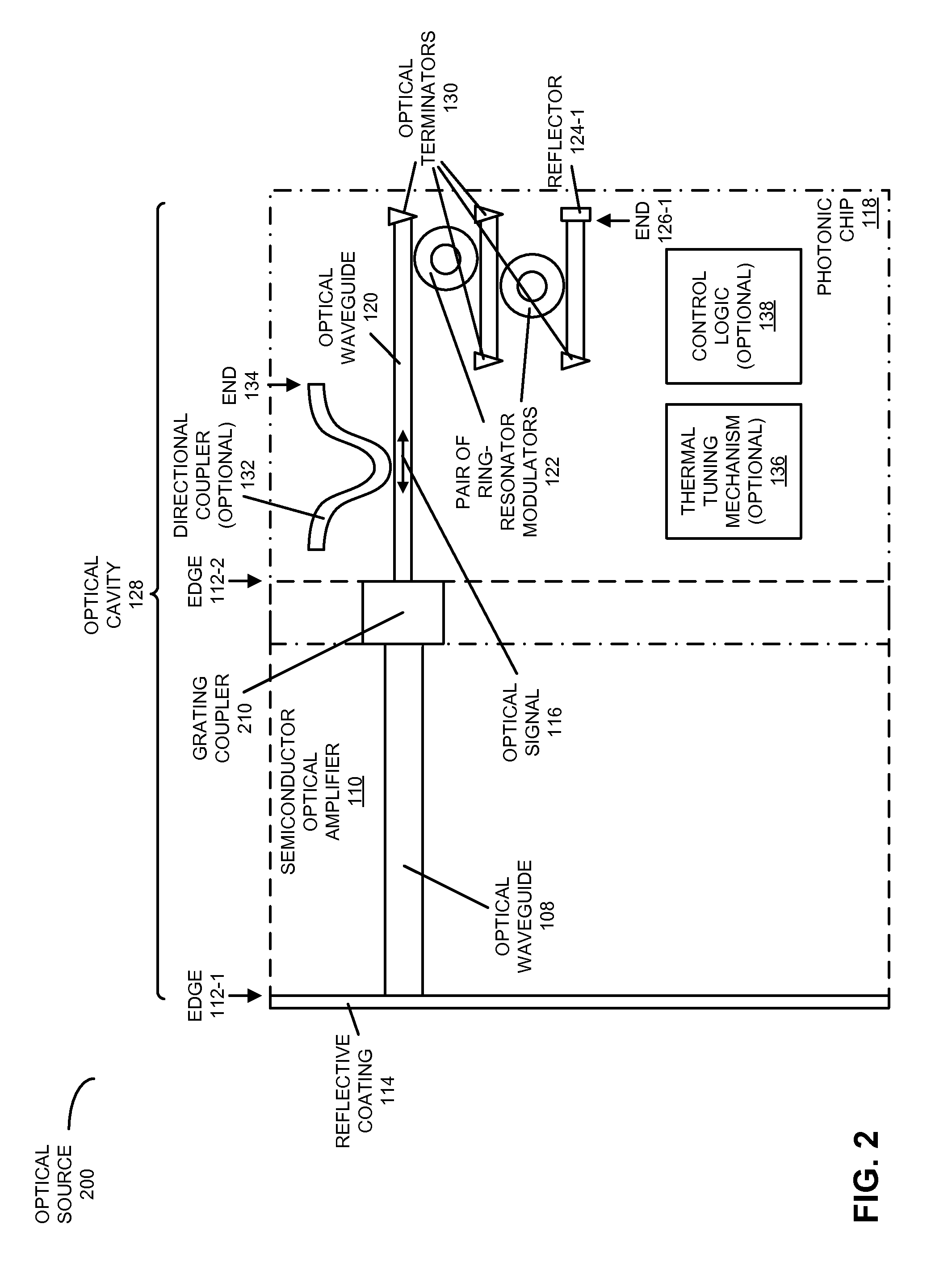
[0029]Embodiments of an optical source (which is sometimes referred to as a ‘ring-modulated laser’), a system that includes the optical source, and a technique for providing an optical signal are described. The optical source includes a semiconductor optical amplifier, with a semiconductor other than silicon, which provides a gain medium. In addition, a photonic chip, optically coupled to the semiconductor optical amplifier, includes: an optical waveguide that conveys the optical signal; and a pair of ring-resonator modulators that modulates the optical signal. Furthermore, the pair of ring-resonator modulators is included within an optical cavity in the optical source. For example, the optical cavity may be defined by a reflective coating on one edge of the semiconductor optical amplifier and a reflector on one end of the optical waveguide. Alternatively, the optical cavity may be defined by reflectors on ends of the optical waveguide.

[0030]By including the pair of ring-resonator m...


PUM


Abstract

An optical source is described. This optical source includes a semiconductor optical amplifier, with a semiconductor other than silicon, which provides a gain medium. In addition, a photonic chip, optically coupled to the semiconductor optical amplifier, includes: an optical waveguide that conveys the optical signal; and a pair of ring-resonator modulators that modulate the optical signal. Furthermore, the pair of ring-resonator modulators is included within an optical cavity in the optical source. For example, the optical cavity may be defined by a reflective coating on one edge of the semiconductor optical amplifier and a reflector on one end of the optical waveguide. Alternatively, the optical cavity may be defined by reflectors on ends of the optical waveguide.

Description

GOVERNMENT LICENSE RIGHTS[0001]This invention was made with Government support under Agreement No. HR0011-08-9-0001 awarded by DARPA. The Government has certain rights in the invention.BACKGROUND[0002]1. Field[0003]The present disclosure relates to the design of an optical source. More specifically, the present disclosure relates to the design of an optical source that includes ring-resonator modulators within an optical cavity.[0004]2. Related Art[0005]Silicon photonics is a promising technology that can provide large communication bandwidth, low latency and low power consumption for inter-chip and intra-chip connections or optical links. A key component for a silicon-photonic optical link is an efficient high-speed optical modulator, which is used to convert a high-speed electrical data signal into an optical signal. For example, optical modulators are often used with continuous-wave optical sources, such as lasers. The requirements for an optical modulator are: high speed, low po...

Claims


Application Information

Patent Timeline
Patent Type & Authority Applications(United States)
IPC IPC(8): H01S5/10H01S5/22H01S5/12
CPCH01S5/2214H01S5/1071H01S5/0261H01S5/0265H01S5/0287H01S5/1032H01S5/12H01S5/021H01S5/142
Inventor LI, GUOLIANGKRISHNAMOORTHY, ASHOK V.ZHENG, XUEZHELUO, YING L.
Owner ORACLE INT CORP
Why Eureka
Try Eureka