
Method and device for characterizing an electron beam

a technology of electron beam and electron beam, which is applied in the direction of additive manufacturing process, manufacturing tools, instruments, etc., can solve the problems of affecting the quality of the material, and requiring a relatively high beam power for starting the glow of metal, so as to achieve the effect of improving the manufacturing of three-dimensional objects

Active Publication Date: 2016-07-21
ARCAM AB
View PDF3 Cites 91 Cited by
  • Summary
  • Abstract
  • Description
  • Claims
  • Application Information

AI Technical Summary

Benefits of technology

The present invention provides a method for calibrating and verifying an electron beam that addresses the problems associated with previous methods. This ensures that the electron beam is accurate and reliable in its use.

Problems solved by technology

Firstly it is time consuming since it takes some time until the metal starts to glow.
Secondly it requires a relatively high beam power for starting the metal to glow.
Thirdly, the metal which has been glowing may have been locally damaged or at least locally changed its material characteristics.
Furthermore there is not a straightforward relationship between the glow of the material and the power of the electron beam.

Method used


Image

  • Method and device for characterizing an electron beam
  • Method and device for characterizing an electron beam
  • Method and device for characterizing an electron beam

Examples


Embodiment Construction

[0055]Various example embodiments of the present invention will now be described more fully hereinafter with reference to the accompanying drawings, in which some, but not all embodiments of the invention are shown. Indeed, embodiments of the invention may be embodied in many different forms and should not be construed as limited to the embodiments set forth herein. Rather, these embodiments are provided so that this disclosure will satisfy applicable legal requirements. Unless otherwise defined, all technical and scientific terms used herein have the same meaning as commonly known and understood by one of ordinary skill in the art to which the invention relates. The term “or” is used herein in both the alternative and conjunctive sense, unless otherwise indicated. Like numbers refer to like elements throughout.

[0056]To facilitate the understanding of this invention, a number of terms are defined below. Terms defined herein have meanings as commonly understood by a person of ordinar...


PUM

PropertyMeasurementUnit
Timeaaaaaaaaaa
Sizeaaaaaaaaaa
Shapeaaaaaaaaaa

Abstract

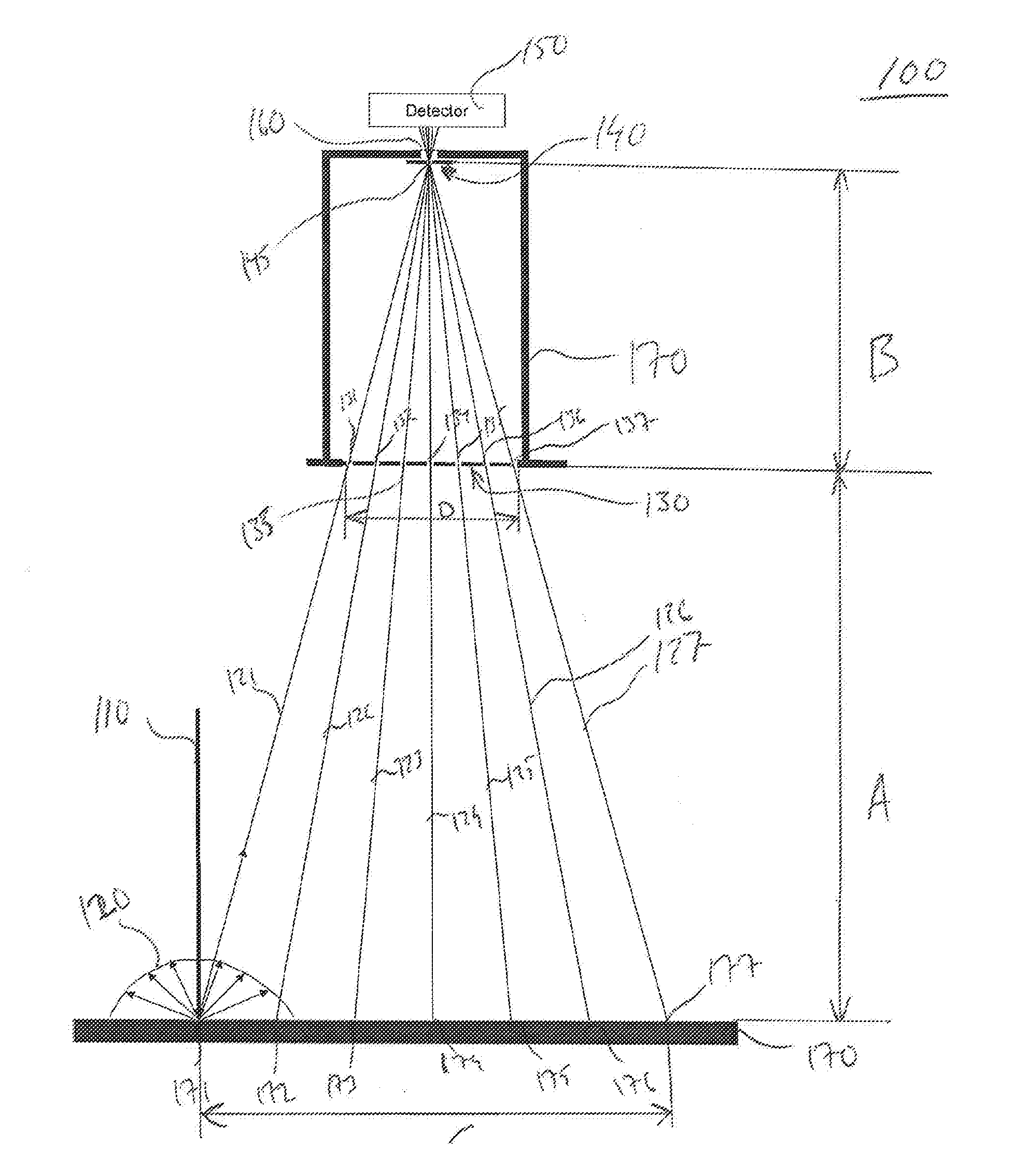
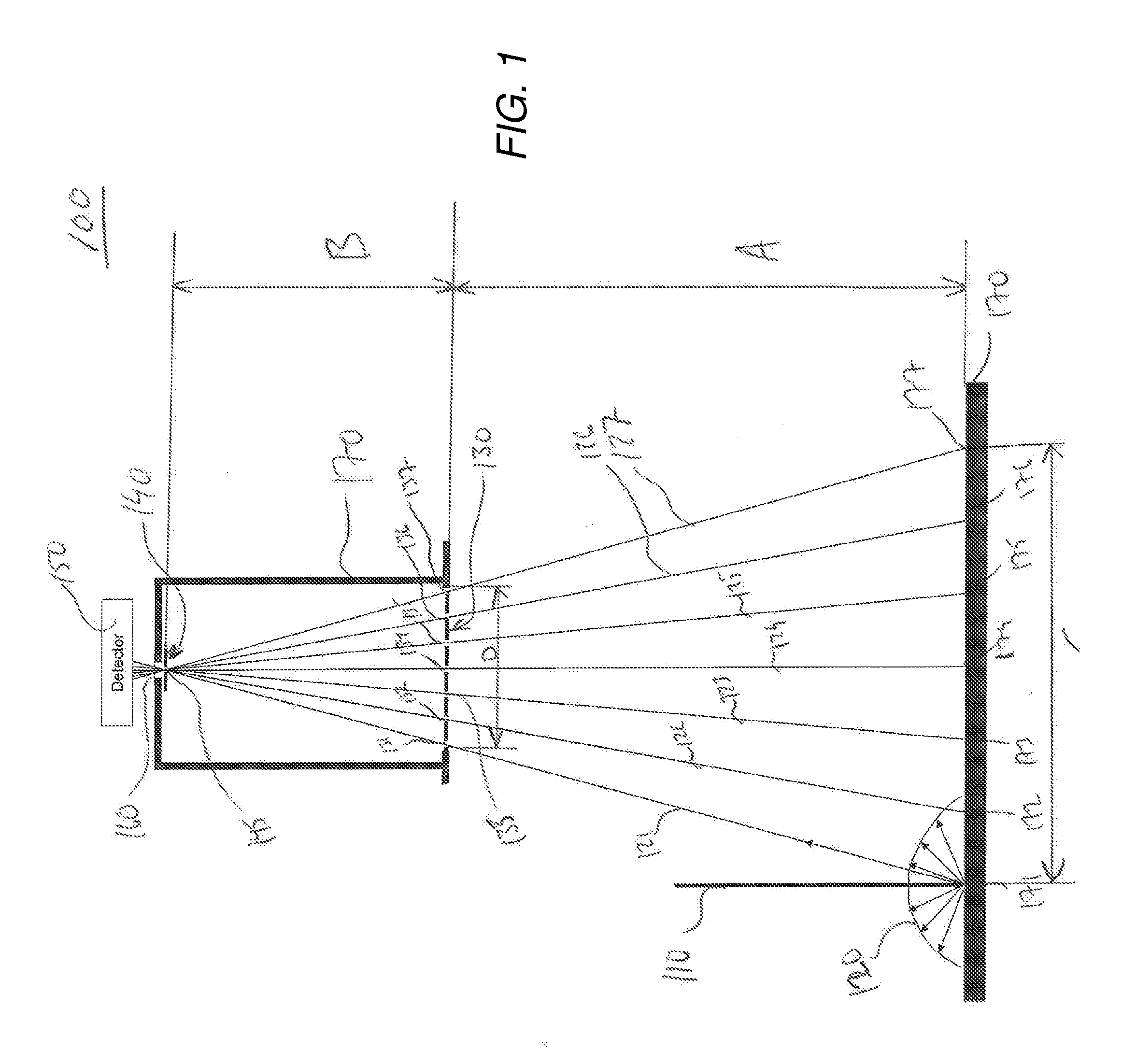
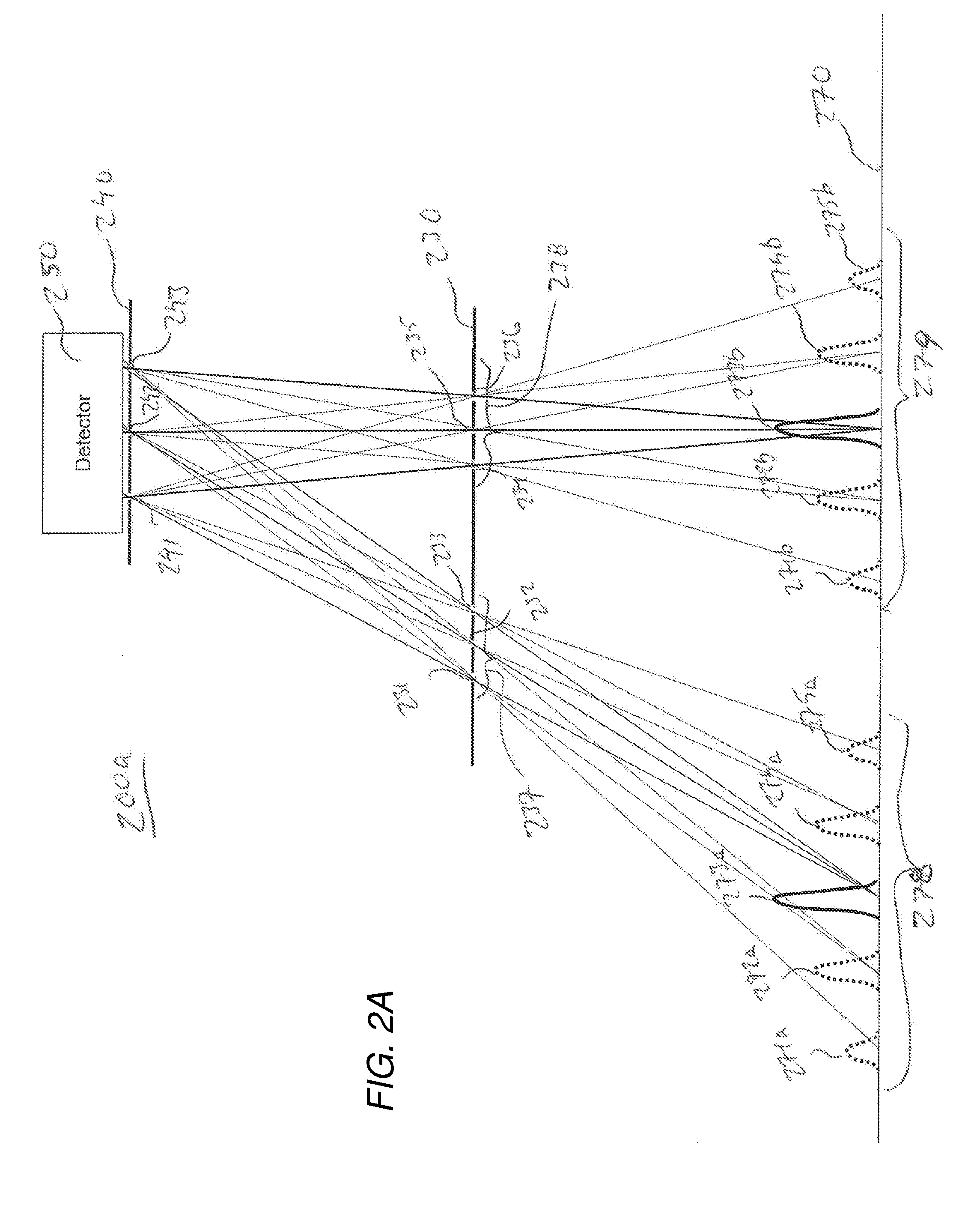
A device for detecting X-rays radiated out of a substrate surface, said device comprising at least one X-ray detector, a resolver grating and a modulator grating, said resolver grating with at least one opening facing towards said X-ray detector is arranged in front of said X-ray detector. Said modulator grating is provided between said resolver grating and said substrate at a predetermined distance from said resolver grating and said substrate, where said modulator grating having a plurality of openings in at least a first direction, wherein said x-rays from said surface is spatially modulated with said modulator grating and resolver grating.

Description

CROSS-REFERENCE TO RELATED APPLICATIONS[0001]This application claims priority to and the benefit of U.S. Provisional Patent Application Ser. No. 62 / 106,089, filed Jan. 21, 2015, the contents of which as are hereby incorporated by reference in their entirety.BACKGROUND[0002]1. Technical Field[0003]The present invention relates to an improved method for characterizing an electron beam.[0004]2. Related Art[0005]Freeform fabrication or additive manufacturing is a method for forming three-dimensional articles through successive fusion of chosen parts of powder layers applied to a work plate. A method and apparatus according to this technique is disclosed in U.S. Pat. No. 7,713,454.[0006]Such an apparatus may comprise a work table on which the three-dimensional article is to be formed, a powder dispenser, arranged to lay down a thin layer of powder on the work table for the formation of a powder bed, an energy beam source for delivering an energy beam spot to the powder whereby fusion of ...

Claims


Application Information

Patent Timeline
IPC IPC(8): H01J37/304H01J37/244B23K15/00H01J37/305
CPCH01J37/304H01J37/305H01J37/244B23K15/0086H01J2237/3128H01J2237/30433H01J2237/30472H01J2237/24514H01J2237/063B33Y30/00B23K15/0013B23K15/002B23K15/0026B33Y10/00B33Y40/00B33Y50/02B23K15/02B28B1/001B28B17/00B28B17/0081G01T1/295H01J37/09H01J37/30H01J37/3005H01J37/3045H01J37/317H01J2237/0453H01J2237/2445H01J2237/2448H01J2237/3045H01J2237/2826Y02P10/25B22F10/00B22F12/55B22F12/90B22F12/44B22F10/31B22F12/49B22F10/28B29C64/153B29C64/393B29C64/364
Inventor LOCK, TOMAS
Owner ARCAM AB
Learn More