Fibrous Structures Comprising a Surface Care Composition and Methods for Making and Using Same

Active Publication Date: 2016-07-28
THE PROCTER & GAMBNE CO
6 Cites 1 Cited by

AI-Extracted Technical Summary

Problems solved by technology

Bathrooms are also problematic, having a tendency to harbor the foregoing pathogenic bacteria on surfaces such as toilets, including flush handles, faucet handles, sinks, bathtubs (including drains), showers, floors, and any other type of bathroom surface.
Even further, moist surfaces such as kitchen and bath sponges or other cleaning implements are generally most susceptible to the colonization of these and other bacteria.
Unfortunately, consumers often use these contaminated implements in an attempt to clean and/or treat and/or disinfect surfaces, particularly those in the kitchen and bathroom, not realizing that such attempts are counter-productive and often result in introducing further bacterial contamination instead of disinfection.
Moist skin surfaces, such as skin susceptible to diaper rash in infants and pre-school children are also particularly susceptible.
Unfortunately, in addition to counter-productive techniques such as using contaminated cleaning devices such as sponges, other techniques have limited efficacy.
Diaper rash and other infections on skin are still common problems that are difficult to manage.
However, such a fibrous structure may require special packaging to maintain the effectiveness of the bacteriophage.
Furthermore, fibrous structure comprising a liquid composition will require special packaging to prevent the liquid composition from drying out during distribution of the product from the manufacturer to the consumer.
However, such a system might require special packaging or bottling of the liquid composition comprising the bacteriophage to maintain the effectiveness of the bacteriophage until application of the liquid composition to a fibrous structure at the time of use.
One problem with the known fibrous structures is that they might require the use of a liquid composition comprising bacteriophage, which necessitates the use of special packaging to maintain the effectiveness of the bacteriophage until use or during distribution and storage of the liquid composition.
Furthermore, consumers find it inconvenient to have to have both a liquid composition comprising bacteriophage and an appropriate fibrous structure to reduce or eliminate these bacteria on surfaces.
In addition to the described problems, bacteriophage a...

Method used

[0049]In one example of the present invention, “fiber” refers to papermaking fibers. Papermaking fibers useful in the present invention include cellulosic fibers commonly known as wood pulp fibers. Applicable wood pulps include chemical pulps, such as Kraft, sulfite, and sulfate pulps, as well as mechanical pulps including, for example, groundwood, thermomechanical pulp and chemically modified thermomechanical pulp. Chemical pulps, however, may be preferred since they impart a superior tactile sense of softness to tissue sheets made therefrom. Pulps derived from both deciduous trees (hereinafter, also referred to as “hardwood”) and coniferous trees (hereinafter, also referred to as “softwood”) may be utilized. The hardwood and softwood fibers can be blended, or alternatively, can be deposited in layers to provide a stratified web. U.S. Pat. No. 4,300,981 and U.S. Pat. No. 3,994,771 are incorporated herein by reference for the purpose of disclosing layering of hardwood and softwood fibers. Also applicable to the present invention are fibers derived from recycled paper, which may contain any or all of the above categories as well as other non-fibrous materials such as fillers and adhesives used to facilitate the original papermaking.
[0058]The sanitary tissue products of the present invention may be in the form of sanitary tissue product rolls. Such sanitary tissue product rolls may comprise a plurality of connected, but perforated sheets of fibrous structure, that are separably dispensable from adjac...

Benefits of technology

[0018]One solution to the problems identified above is a dry fibrous structure comprising a surface care composition comprising one or more b...

Abstract

Fibrous structures containing a surface care composition, and more particularly dry fibrous structures containing a surface care composition comprising one or more bacteriophage, methods of making same, and methods for treating surfaces using same are provided.

Application Domain

BiocideAnimal repellants +1

Technology Topic

Biomedical engineeringFiber +1

Image

  • Fibrous Structures Comprising a Surface Care Composition and Methods for Making and Using Same
  • Fibrous Structures Comprising a Surface Care Composition and Methods for Making and Using Same
  • Fibrous Structures Comprising a Surface Care Composition and Methods for Making and Using Same

Examples

  • Experimental program(3)

Example

Example 1
[0120]This example describes the feasibility of transferring bacteriophage from a disposable paper towel onto a solid surface.
[0121]Preparation [0122] 1. Prepare carriers [0123] a. Dilute fetal bovine serum to 5% (if at 100% add 1 mL to 19 mL sterile water) [0124] b. Dip 7 sterile glass slides into serum-to replicate organic load found on a surface [0125] c. Allow to dry at 37° C. for 40 minutes [0126] 2. Spray 5 BOUNTY® paper towels (commercially available from The Procter & Gamble Company, Cincinnati, Ohio) with SALMOLYSE® bacteriophage cocktail (109 PFU/mL, 10 sprays ˜3 mL) (commercially available from Intralytics, Inc., Baltimore, Md.). [0127] 3. Fold paper towel in half three times [0128] 4. Wipe paper towel across the glass slide five times [0129] a. Complete a total of 5 sample replicates [0130] 5. Place slide into 20 mL sterile saline in a 50 mL conical [0131] a. Vortex 30s [0132] b. Pass saline through 0.2 um filter and collect filtrate [0133] 6. Complete negative control [0134] a. Wipe slide with untreated paper towel and complete like above [0135] 7. Complete positive controls [0136] a. Add 50 ul of phage directly onto slide [0137] i. Place slide into 50 mL conical with 20 mL sterile saline [0138] ii. Vortex [0139] iii. Filter [0140] 8. Complete plaque assay (using Salmonella Enteritidis 781) [0141] a. Complete, 10 fold serial dilutions on all test samples [0142] use each dilution [0143] b. Negative control no diluting needed [0144] c. Positive controls complete 4, 10 fold serial dilutions [0145] assay dilutions 2, 3, 4
[0146]Results
TABLE 1 PFU applied PFU per sq cm PFU per surface used to wipe 9.30E+09 1.26E+07 1.16E+09
TABLE 2 Plate Sample Dilution Count PFU/slide LOG Phage Titer 7 31 3.10E+09 9.4914 Positive Control 4 82 1.64E+08 8.2148 Negative Control 0 0 0.00E+00 0.0000 Replicate 1 1 18 3.60E+04 4.5563 Replicate 2 1 153 3.06E+05 5.4857 Replicate 3 1 22 4.40E+04 4.6435 Replicate 4 1 175 3.50E+05 5.5441 Replicate 5 2 30 6.00E+05 5.7782 Average: 2.67E+05 5.2015
As shown in Tables 1 and 2 above, bacteriophage can be successfully transferred from a paper towel onto a solid surface. Here, about 5 of the possible 8 logs of bacteriophage present on the paper towel are transferred from the paper towel onto the slide. This testing is completed with paper towel that had not completely dried and carriers that are also partially wet. While paper towels are typically used on moist surfaces, the paper towel itself is initially dry.

Example

Example 2
[0147]describes the impact on the amount of bacteriophage transferred to the surface based on whether the paper towel is pre-wetted or dry during use and whether the solid surface that is wiped is pre-wetted or dry during wiping.
[0148]Preparation [0149] 1. Prepare carriers [0150] a. Dilute fetal bovine serum to 5% [0151] b. Dip 22 sterile glass slides into serum-to replicate organic load found on a surface [0152] c. Allow to dry [0153] 2. Spray 20 BOUNTY® paper towels (commercially available from The Procter & Gamble Company, Cincinnati, Ohio) with T4 bacteriophage (109 PFU/mL a 1:10 dil of lysate, titer to confirm concentration) [0154] a. 10 sprays per paper towel (˜3 mL) [0155] b. Fold paper towel in half three times [0156] 3. With paper towel still wet, wipe paper towel across the DRY glass slide five times [0157] a. Complete a total of 5 sample replicates [0158] 4. Place slide into 20 mL sterile saline in a 50 mL conical [0159] a. Vortex 30s [0160] b. Pass saline through 0.2 um filter and collect filtrate [0161] 5. Mist 5 carriers with PBS spray to wet (2 sprays) [0162] a. With paper towel still wet, wipe paper towel across the WET glass slide five times [0163] b. Complete a total of 5 sample replicates [0164] 6. Place slide into 20 mL sterile saline in a 50 mL conical [0165] a. Vortex 30s [0166] b. Pass saline through 0.2 um filter and collect filtrate [0167] 7. Allow remaining 10 paper towels to dry [0168] 8. Wipe DRY paper towel across the DRY glass slide five times [0169] a. Complete a total of 5 sample replicates [0170] 9. Place slide into 20 mL sterile saline in a 50 mL conical [0171] a. Vortex 30s [0172] b. Pass saline through 0.2 um filter and collect filtrate [0173] 10. Mist 5 carriers with PBS spray to wet (2 sprays) [0174] 11. Wipe DRY paper towel across the WET glass slide five times [0175] a. Complete a total of 5 sample replicates [0176] 12. Place slide into 20 mL sterile saline in a 50 mL conical [0177] a. Vortex 30s [0178] b. Pass saline through 0.2 um filter and collect filtrate [0179] 13. Complete negative control [0180] a. Wipe 1 carrier with untreated paper towel and complete like above [0181] 14. Place slide into 20 mL sterile saline in a 50 mL conical [0182] a. Vortex 30s [0183] b. Pass saline through 0.2 um filter and collect filtrate [0184] 14. Complete positive control [0185] a. Add 100 ul of phage directly onto slide (same sample as sprayed onto paper towels) [0186] b. Apply so that it covers about the same area of the slide as what you wiped [0187] c. Allow to dry a bit (no obvious puddles) [0188] i. Place slide into 50 mL conical with 20 mL sterile saline [0189] ii. Vortex [0190] iii. Filter [0191] 15. Complete plaque assay (using E. coli) [0192] a. Complete 4, 10 fold serial dilutions on all test samples [0193] use each dilution [0194] b. Negative control no diluting needed [0195] c. Positive controls complete 4, 10 fold serial dilutions [0196] assay dilutions 2, 3, 4
Results
[0197]
TABLE 4 Dry Towel −> Plate Wet Surface Dilution Count Pfu/slide LOG Replicate 1 0 100 2.00E+04 4.3010 Replicate 2 0 7 1.40E+03 3.1461 Replicate 3 0 171 3.42E+04 4.5340 Replicate 4 0 420 8.40E+04 4.9243 Replicate 5 0 163 3.26E+04 4.5132 Average: 3.44E+04 4.2837
TABLE 3 Dry Towel −> Plate Dry Surface Dilution Count Pfu/slide LOG Replicate 1 0 66 1.32E+04 4.1206 Replicate 2 0 143 2.86E+04 4.4564 Replicate 3 0 34 6.80E+03 3.8325 Replicate 4 0 72 1.44E+04 4.1584 Replicate 5 0 79 1.58E+04 4.1987 Average: 1.58E+04 4.1533
TABLE 6 Wet Towel −> Plate Wet Surface Dilution Count Pfu/slide LOG Replicate 1 0 428 8.56E+04 4.9325 Replicate 2 0 281 5.62E+04 4.7497 Replicate 3 0 468 9.36E+04 4.9713 Replicate 4 0 238 4.76E+04 4.6776 Replicate 5 0 368 7.36E+04 4.8669 Average: 7.13E+04 4.8396
TABLE 5 Wet Towel −> Plate Dry Surface Dilution Count Pfu/slide LOG Replicate 1 0 232 4.64E+04 4.6665 Replicate 2 0 406 8.12E+04 4.9096 Replicate 3 0 206 4.12E+04 4.6149 Replicate 4 0 298 5.96E+04 4.7752 Replicate 5 0 178 3.56E+04 4.5514 Average: 5.28E+04 4.7035
In this Example 2, the highest amount of bacteriophage transferred from a paper towel to a surface occurs when both the paper towel and the surface are pre-wetted (water content of 20% or greater by weight of the dry fibrous structure at time of use). The least amount of transfer is seen when both the paper towel and the surface are dry (water content less than 20% by weight of the dry fibrous structure at time of use). Overall, using a dry towel on a wet or dry surface has a similar level of bacteriophage transfer. A similar level of bacteriophage transfer is also seen when a pre-wetted paper towel is used on a wet or dry surface.
NON-LIMITING EXAMPLES OF DRY FIBROUS STRUCTURES

Example

Example 3
Paper Towel
[0198]Examples of dry fibrous structures; namely, paper towels, are produced utilizing a cellulosic pulp fiber furnish consisting of about 55% refined softwood furnish consisting of about 44% Northern Bleached Softwood Kraft (Bowater), 44% Northern Bleached Softwood Kraft (Celgar) and 12% Southern Bleached Softwood Kraft (Alabama River Softwood, Weyerhaeuser); about 30% of unrefined hardwood Eucalyptus Bleached Kraft consisting of about 80% (Fibria) and 20% NBHK (Aspen) (Peace River); and about 15% of an unrefined furnish consisting of a blend of about 27% Northern Bleached Softwood Kraft (Bowater), 27% Northern Bleached Softwood Kraft (Celgar), 42% Eucalyptus Bleached Kraft (Fibria) and 7% Southern Bleached Kraft (Alabama River Softwood, Weyerhaeuser). The 55% refined softwood is refined as needed to maintain target wet burst at the reel. Any furnish preparation and refining methodology common to the papermaking industry can be utilized.
[0199]A 3% active solution Kymene 5221 is added to the refined softwood line prior to an in-line static mixer and 1% active solution of Wickit 1285, an ethoxylated fatty alcohol available from Ashland Inc. is added to the unrefined Eucalyptus Bleached Kraft (Fibria) hardwood furnish. The addition levels are 21 and 1 lbs active/ton of paper, respectively.
[0200]The refined softwood and unrefined hardwood and unrefined NBSK/SSK/Eucalyptus bleached kraft/NDHK thick stocks are then blended into a single thick stock line followed by addition of 1% active carboxymethylcellulose (CMC-Finnfix) solution at 7 lbs active/ton of paper towel, and optionally, a softening agent may be added.
[0201]The thick stock is then diluted with white water at the inlet of a fan pump to a consistency of about 0.15% based on total weight of softwood, hardwood and simulated broke fiber. The diluted fiber slurry is directed to a non layered configuration headbox such that the wet web formed onto a Fourdrinier wire (foraminous wire). Optionally, a fines retention/drainage aid may be added to the outlet of the fan pump.
[0202]Dewatering occurs through the Fourdrinier wire and is assisted by deflector and vacuum boxes. The Fourdrinier wire is of a 5-shed, satin weave configuration having 87 machine-direction and 76 cross-direction monofilaments per inch, respectively. The speed of the Fourdrinier wire is about 750 fpm (feet per minute).
[0203]The embryonic wet web is transferred from the Fourdrinier wire at a fiber consistency of about 24% at the point of transfer, to a belt, such as a patterned belt through-air-drying resin carrying fabric. In the present case, the speed of the patterned through-air-drying fabric is approximately the same as the speed of the Fourdrinier wire. In another case, the embryonic wet web may be transferred to a patterned belt and/or fabric that is traveling slower, for example about 20% slower than the speed of the Fourdrinier wire (for example a wet molding process).
[0204]Further de-watering is accomplished by vacuum assisted drainage until the web has a fiber consistency of about 30%.
[0205]While remaining in contact with the patterned belt, the web is pre-dried by air blow-through pre-dryers to a fiber consistency of about 65% by weight.
[0206]After the pre-dryers, the semi-dry web is transferred to a Yankee dryer and adhered to the surface of the Yankee dryer with a sprayed creping adhesive. The creping adhesive is an aqueous dispersion with the actives consisting of about 75% polyvinyl alcohol, and about 25% CREPETROL® R6390. Optionally a crepe aid consisting of CREPETROL® A3025 may be applied. CREPETROL® R6390 and CREPETROL® A3025 are commercially available from Ashland Inc. (formerly Hercules Inc.). The creping adhesive diluted to about 0.15% adhesive solids and delivered to the Yankee surface at a rate of about 2# adhesive solids based on the dry weight of the web. The fiber consistency is increased to about 97% before the web is dry creped from the Yankee with a doctor blade.
[0207]In the present case, the doctor blade has a bevel angle of about 45° and is positioned with respect to the Yankee dryer to provide an impact angle of about 101° and the reel is run at a speed that is about 15% faster than the speed of the Yankee. In another case, the doctor blade may have a bevel angle of about 25° and be positioned with respect to the Yankee dryer to provide an impact angle of about 81° and the reel is run at a speed that is about 10% slower than the speed of the Yankee. The Yankee dryer is operated at a temperature of about 177° C. and a speed of about 800 fpm. The fibrous structure is wound in a roll using a surface driven reel drum having a surface speed of about 656 feet per minute.
[0208]The fibrous structure may be subsequently converted into a two-ply paper towel product having a basis weight of about 45 to 54 g/m2. During the converting operation, a bacteriophage composition may be applied to the fibrous structure to produce a dry fibrous structure (dry paper towel) comprising the bacteriophage composition by any suitable means, for example by printing on the bacteriophage composition to one or more surfaces of the fibrous structure.
Test Methods
[0209]Unless otherwise indicated, all tests described herein including those described under the Definitions section and the following test methods are conducted on samples that have been conditioned in a conditioned room at a temperature of 23° C.±2.2° C. and a relative humidity of 50%±10% for 2 hours prior to the test unless otherwise indicated. Samples conditioned as described herein are considered dry samples (such as “dry fibrous structures”) for purposes of this invention. Further, all tests are conducted in such conditioned room.
Water Content Test Method
[0210]The water (moisture) content present in a fibrous structure is measured using the following Water Content Test Method.
[0211]A fibrous structure or portion thereof (“sample”) is placed in a conditioned room at a temperature of 73° F.±4° F. (about 23° C.±2.2° C.) and a relative humidity of 50%±10% for at least 24 hours prior to testing. The weight of the sample is recorded when no further weight change is detected for at least a 5 minute period. Record this weight as the “equilibrium weight” of the sample. Next, place the sample in a drying oven for 24 hours at 70° C. with a relative humidity of about 4% to dry the sample. After the 24 hours of drying, immediately weigh the sample. Record this weight as the “dry weight” of the sample. The water (moisture) content of the sample is calculated as follows:
% Water ( moisture ) in sample = 100 % × ( Equilibrium weight of sample - Dry weight of sample ) Dry weight of sample
The % Water (moisture) in sample for 3 replicates is averaged to give the reported % Water (moisture) in sample.
Basis Weight Test Method
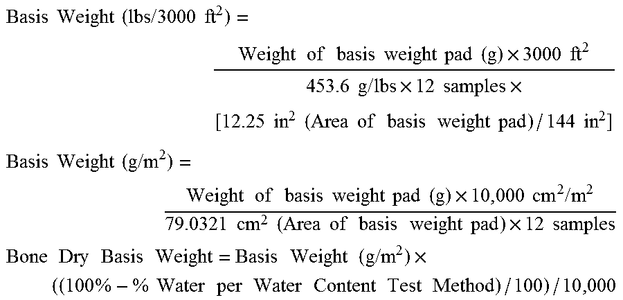
[0212]Basis weight of a fibrous structure sample is measured by selecting twelve (12) individual fibrous structure samples and making two stacks of six individual samples each. If the individual samples are connected to one another vie perforation lines, the perforation lines must be aligned on the same side when stacking the individual samples. A precision cutter is used to cut each stack into exactly 3.5 in.×3.5 in. squares. The two stacks of cut squares are combined to make a basis weight pad of twelve squares thick. The basis weight pad is then weighed on a top loading balance with a minimum resolution of 0.01 g. The top loading balance must be protected from air drafts and other disturbances using a draft shield. Weights are recorded when the readings on the top loading balance become constant. The Basis Weight is calculated as follows:
Basis Weight ( lbs / 3000 ft 2 ) = Weight of basis weight pad ( g ) × 3000 ft 2 453.6 g / lbs × 12 samples × [ 12.25 in 2 ( Area of basis weight pad ) / 144 in 2 ] Basis Weight ( g / m 2 ) = Weight of basis weight pad ( g ) × 10 , 000 cm 2 / m 2 79.0321 cm 2 ( Area of basis weight pad ) × 12 samples Bone Dry Basis Weight = Basis Weight ( g / m 2 ) × ( ( 100 % - % Water per Water Content Test Method ) / 100 ) / 10 , 000
Thickness Method
[0213]Thickness of a fibrous structure and/or sanitary tissue product is measured using a ProGage Thickness Tester (Thwing-Albert Instrument Company, West Berlin, N.J.) with a pressure foot diameter of 2.00 inches (area of 3.14 in2) at a pressure of 95 g/in2. Four (4) samples are prepared by cutting of a usable unit such that each cut sample is at least 2.5 inches per side, avoiding creases, folds, and obvious defects. An individual specimen is placed on the anvil with the specimen centered underneath the pressure foot. The foot is lowered at 0.03 in/sec to an applied pressure of 95 g/in2. The reading is taken after 3 sec dwell time, and the foot is raised. The measure is repeated in like fashion for the remaining 3 specimens. The caliper is calculated as the average caliper of the four specimens and is reported in mils (0.001 in) to the nearest 0.1 mils. Conversion to cm can be made using standard conversion factors.
Density Test Method
[0214]The density of a web sample is measured by dividing the Basis Weight of the web sample by the Thickness of the web sample. Density units are reported as g/cm3.
Tensile Test Method: Peak Elongation, Tensile Strength, TEA and Modulus
[0215]Peak Elongation, Tensile Strength, TEA and Tangent Modulus are measured on a constant rate of extension tensile tester with computer interface (a suitable instrument is the EJA Vantage from the Thwing-Albert Instrument Co. Wet Berlin, N.J.) using a load cell for which the forces measured are within 10% to 90% of the limit of the cell. Both the movable (upper) and stationary (lower) pneumatic jaws are fitted with smooth stainless steel faced grips, 25.4 mm in height and wider than the width of the test specimen. An air pressure of about 60 psi is supplied to the jaws.
[0216]Eight usable units of a fibrous structure sample are divided into two stacks of four samples each. The samples in each stack are consistently oriented with respect to machine direction (MD) and cross direction (CD). One of the stacks is designated for testing in the MD and the other for CD. Using a one inch precision cutter (Thwing Albert JDC-1-10, or similar) cut 4 MD strips from one stack, and 4 CD strips from the other, with dimensions of 1.00 in ±0.01 in wide by 3.0-4.0 in long. Each strip of one usable unit thick will be treated as a unitary specimen for testing.
[0217]Program the tensile tester to perform an extension test, collecting force and extension data at an acquisition rate of 20 Hz as the crosshead raises at a rate of 2.00 in/min (5.08 cm/min) until the specimen breaks. The break sensitivity is set to 80%, i.e., the test is terminated when the measured force drops to 20% of the maximum peak force, after which the crosshead is returned to its original position.
[0218]Set the gauge length to 1.00 inch. Zero the crosshead and load cell. Insert at least 1.0 in of the unitary specimen into the upper grip, aligning it vertically within the upper and lower jaws and close the upper grips. Insert the unitary specimen into the lower grips and close. The unitary specimen should be under enough tension to eliminate any slack, but less than 5.0 g of force on the load cell. Start the tensile tester and data collection. Repeat testing in like fashion for all four CD and four MD unitary specimens.
[0219]Program the software to calculate the following from the constructed force (g) verses extension (in) curve:
[0220]Tensile Strength is the maximum peak force (g) divided by the sample width (in) and reported as g/in to the nearest 1 g/in.
[0221]Adjusted Gauge Length is calculated as the extension measured at 3.0 g of force (in) added to the original gauge length (in).
[0222]Peak Elongation is calculated as the extension at maximum peak force (in) divided by the Adjusted Gauge Length (in) multiplied by 100 and reported as % to the nearest 0.1%
[0223]Total Energy (TEA) is calculated as the area under the force curve integrated from zero extension to the extension at the maximum peak force (g*in), divided by the product of the adjusted Gauge Length (in) and specimen width (in) and is reported out to the nearest 1 g*in/in2. Replot the force (g) verses extension (in) curve as a force (g) verses strain curve. Strain is herein defined as the extension (in) divided by the Adjusted Gauge Length (in).
[0224]Program the software to calculate the following from the constructed force (g) verses strain curve:
[0225]Tangent Modulus (Modulus) is the Modulus at 15 g/cm.
[0226]The Tensile Strength (g/in), Peak Elongation (%), Total Energy (g*in/in2) and Modulus (g/cm), which is the Tangent Modulus at 15 g/cm), are calculated for the four CD unitary specimens and the four MD unitary specimens. Calculate an average for each parameter separately for the CD and MD specimens.
[0227]Calculations:
Geometric Mean Tensile Strength=Square Root of [MD Tensile Strength(g/in)×CD Tensile Strength(g/in)]
Geometric Mean Peak Elongation=Square Root of [MD Elongation (%)×CD Elongation(%)]
Geometric Mean TEA=Square Root of [MD TEA(g*in/in2)×CD TEA(g*in/in2)]
Geometric Mean Modulus=Square Root of [MD Modulus(g/cm)(at 15 g/cm)×CD Modulus(g/cm)(at 15 g/cm)]
Total Dry Tensile Strength(TDT)=MD Tensile Strength(g/in)+CD Tensile Strength(g/in)
Total TEA=MD TEA(g*in/in2)+CD TEA(g*in/in2)
Total Modulus=MD Modulus(g/cm)+CD Modulus(g/cm)
Tensile Ratio=MD Tensile Strength(g/in)/CD Tensile Strength(g/in)
Initial Total Wet Tensile Test Method
[0228]The initial total wet tensile of a dry fibrous structure is determined using a Thwing-Albert EJA Material Tester Instrument, Cat. No. 1350, equipped with 5000 g load cell available from Thwing-Albert Instrument Company, 14 Collings Ave. W. Berlin, N.J. 08091. 10% of the 5000 g load cell is utilized for the initial total wet tensile test. [0229] i. Sample Preparation—A sample strip of dry fibrous structure to be tested [2.54 cm (1 inch) wide by greater than 5.08 cm (2 inches)] long is obtained. [0230] ii. Operation—The test settings for the instrument are: [0231] Crosshead speed—10.16 cm/minute (4.0 inches/minute) [0232] Initial gauge length 2.54 cm (1.0 inch) [0233] Adjust the load cell to read zero plus or minus 0.5 gramsforce (gf) [0234] iii. Testing Samples—One end of the sample strip is placed between the upper jaws of the machine and clamped. After verifying that the sample strip is hanging straight between the lower jaws, clamp the other end of the sample strip in the lower jaws.
[0235]a. Pre-Test—
[0236]Strain the sample strip to 25 gramsforce (+/−10 gramsforce) at a strain rate of 3.38 cm/minute (1.33 inches/minute) prior to wetting the sample strip. The distance between the upper and lower jaws now being greater than 2.54 cm (1.0 inch). This distance now becomes the new zerostrain position for the forthcoming wet test described below.
[0237]b. Wet Test—
[0238]While the sample strip is still at 25 gramsforce (+1-10 gramsforce), it is wetted, starting near the upper jaws, a water/0.1% Pegosperse® ML200 (available from Lonza Inc. of Allendale, N.J.) solution [having a temperature of about 73° F.±4° F. (about 23° C.±2.2° C.)] is delivered to the sample strip via a 2 mL disposable pipette. Do not contact the sample strip with the pipette and do not damage the sample strip by using excessive squirting pressure. The solution is continuously added until the sample strip is visually determined to be completely saturated between the upper and lower jaws. At this point, the load cell is re-adjusted to read 0±0.5 gramsforce. The sample strip is then strained at a rate of 10.16 cm/minute (4 inches/minute) and continues until the sample strip is strained past its failure point (failure point being defined as the point on the force-strain curve where the sample strip falls to 50% of its peak strength after it has been strained past its peak strength). The straining of the sample strip is initiated between 5-10 seconds after the sample is initially wetted. The initial result of the test is an array of data points in the form of load (gramsforce) versus strain (where strain is calculated as the crosshead displacement (cm of jaw movement from starting point) divided by the initial separation distance (cm) between the upper and lower jaws after the pre-test.
[0239]The sample is tested in two orientations, referred to here as MD (machine direction, i.e., in the same direction as the continuously wound reel and forming fabric) and CD (cross-machine direction, i.e., 90° from MD). The MD and CD initial wet tensile strengths are determined using the above equipment and the initial total wet tensile values are calculated in the following manner:
ITWT(g/inch)=Peak LoadMD(gf)/1(inchwidth)+Peak LoadCD(gf)/1(inchwidth)
Percent Compressibility Test Method
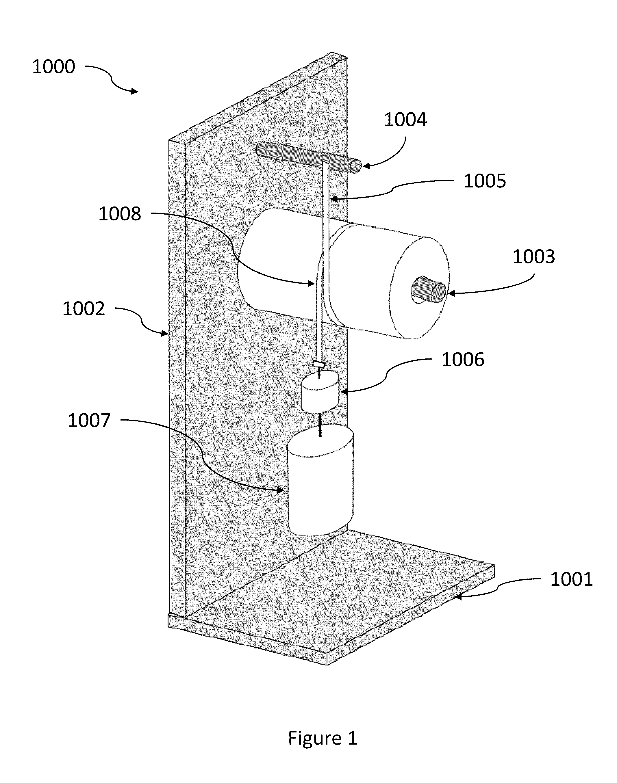
[0240]Percent Roll Compressibility (Percent Compressibility) is determined using the Roll Diameter Tester 1000 as shown in FIG. 1. It is comprised of a support stand made of two aluminum plates, a base plate 1001 and a vertical plate 1002 mounted perpendicular to the base, a sample shaft 1003 to mount the test roll, and a bar 1004 used to suspend a precision diameter tape 1005 that wraps around the circumference of the test roll. Two different weights 1006 and 1007 are suspended from the diameter tape to apply a confining force during the uncompressed and compressed measurement. All testing is performed in a conditioned room maintained at about 23° C.±2 C.° and about 50%±2% relative humidity.
[0241]The diameter of the test roll is measured directly using a Pi® tape or equivalent precision diameter tape (e.g. an Executive Diameter tape available from Apex Tool Group, LLC, Apex, N.C., Model No. W606PD) which converts the circumferential distance into a diameter measurement so the roll diameter is directly read from the scale. The diameter tape is graduated to 0.01 inch increments with accuracy certified to 0.001 inch and traceable to NIST. The tape is 0.25 in wide and is made of flexible metal that conforms to the curvature of the test roll but is not elongated under the 1100 g loading used for this test. If necessary the diameter tape is shortened from its original length to a length that allows both of the attached weights to hang freely during the test, yet is still long enough to wrap completely around the test roll being measured. The cut end of the tape is modified to allow for hanging of a weight (e.g. a loop). All weights used are calibrated, Class F hooked weights, traceable to NIST.
[0242]The aluminum support stand is approximately 600 mm tall and stable enough to support the test roll horizontally throughout the test. The sample shaft 1003 is a smooth aluminum cylinder that is mounted perpendicularly to the vertical plate 1002 approximately 485 mm from the base. The shaft has a diameter that is at least 90% of the inner diameter of the roll and longer than the width of the roll. A small steal bar 1004 approximately 6.3 mm diameter is mounted perpendicular to the vertical plate 1002 approximately 570 mm from the base and vertically aligned with the sample shaft. The diameter tape is suspended from a point along the length of the bar corresponding to the midpoint of a mounted test roll. The height of the tape is adjusted such that the zero mark is vertically aligned with the horizontal midline of the sample shaft when a test roll is not present.
[0243]Condition the samples at about 23° C.±2 C.° and about 50%±2% relative humidity for 2 hours prior to testing. Rolls with cores that are crushed, bent or damaged should not be tested. Place the test roll on the sample shaft 1003 such that the direction the paper was rolled onto its core is the same direction the diameter tape will be wrapped around the test roll. Align the midpoint of the roll's width with the suspended diameter tape. Loosely loop the diameter tape 1004 around the circumference of the roll, placing the tape edges directly adjacent to each other with the surface of the tape lying flat against the test sample. Carefully, without applying any additional force, hang the 100 g weight 1006 from the free end of the tape, letting the weighted end hang freely without swinging. Wait 3 seconds. At the intersection of the diameter tape 1008, read the diameter aligned with the zero mark of the diameter tape and record as the Original Roll Diameter to the nearest 0.01 inches. With the diameter tape still in place, and without any undue delay, carefully hang the 1000 g weight 1007 from the bottom of the 100 g weight, for a total weight of 1100 g. Wait 3 seconds. Again read the roll diameter from the tape and record as the Compressed Roll Diameter to the nearest 0.01 inch. Calculate percent compressibility to the according to the following equation and record to the nearest 0.1%:
% Compressibility = ( Original Roll Diameter ) - ( Compressed Roll Diameter ) Original Roll Diameter × 100
[0244]Repeat the testing on 10 replicate rolls and record the separate results to the nearest 0.1%. Average the 10 results and report as the Percent Compressibility to the nearest 0.1%.
[0245]The dimensions and values disclosed herein are not to be understood as being strictly limited to the exact numerical values recited. Instead, unless otherwise specified, each such dimension is intended to mean both the recited value and a functionally equivalent range surrounding that value. For example, a dimension disclosed as “40 μm” is intended to mean “about 40 μm.”
[0246]Every document cited herein, including any cross referenced or related patent or application, is hereby incorporated herein by reference in its entirety unless expressly excluded or otherwise limited. The citation of any document is not an admission that it is prior art with respect to any invention disclosed or claimed herein or that it alone, or in any combination with any other reference or references, teaches, suggests or discloses any such invention. Further, to the extent that any meaning or definition of a term in this document conflicts with any meaning or definition of the same term in a document incorporated by reference, the meaning or definition assigned to that term in this document shall govern.
[0247]While particular embodiments of the present invention have been illustrated and described, it would be obvious to those skilled in the art that various other changes and modifications can be made without departing from the spirit and scope of the invention. It is therefore intended to cover in the appended claims all such changes and modifications that are within the scope of this invention.

PUM

no PUM

Description & Claims & Application Information

We can also present the details of the Description, Claims and Application information to help users get a comprehensive understanding of the technical details of the patent, such as background art, summary of invention, brief description of drawings, description of embodiments, and other original content. On the other hand, users can also determine the specific scope of protection of the technology through the list of claims; as well as understand the changes in the life cycle of the technology with the presentation of the patent timeline. Login to view more.

Similar technology patents

Therapeutic placebo enhancement of commonly-used medications

InactiveUS6855324B2enhanced effectivenessmaintain effectiveness
Owner:SANDLER ADRIAN

Methods and materials to treat junctional and pelvic hemorrhage

InactiveUS20160271293A1enhanced effectivenessmaintain effectiveness
Owner:ZUGATES GREGORY T +8

Software defined radio unit and vehicular information system

InactiveUS20060161314A1reduces conveniencemaintain effectiveness
Owner:HITACHI LTD

Classification and recommendation of technical efficacy words

  • maintain effectiveness

Software defined radio unit and vehicular information system

InactiveUS20060161314A1reduces conveniencemaintain effectiveness
Owner:HITACHI LTD

Therapeutic placebo enhancement of commonly-used medications

InactiveUS6855324B2enhanced effectivenessmaintain effectiveness
Owner:SANDLER ADRIAN

Methods and materials to treat junctional and pelvic hemorrhage

InactiveUS20160271293A1enhanced effectivenessmaintain effectiveness
Owner:ZUGATES GREGORY T +8
Why Eureka
Try Eureka