Flexible electrical power cable

a flexible, electrical power cable technology, applied in the direction of cables, flat/ribbon cables, insulated conductors, etc., can solve the problems of high material cost, difficult to bend, heavy power cables,

Active Publication Date: 2016-07-28
COMMSCOPE TECH LLC
View PDF17 Cites 4 Cited by
  • Summary
  • Abstract
  • Description
  • Claims
  • Application Information

AI Technical Summary

Benefits of technology

[0020]The inventor has recognized that the prior accepted circular cross section power cable design paradigm results in unnecessarily large power cables with reduced bend radius, excess metal material costs and / or significant additional manufacturing process requirements.
[0031]One skilled in the art will appreciate that in addition to the aluminum versus copper material cost savings, a weight savings for an electrical cable with aluminum conductors installed upon a radio tower is especially significant, as an overall weight savings enables a corresponding reduction in the overall design load of the antenna / transceiver systems installed upon the radio tower / support structure. Further, the improved bending characteristics of the flexible electrical power cable may simplify installation in close quarters and / or in remote locations such as atop radio towers where conventional bending tools may not be readily available and / or easily applied. Finally, because complex stranding structures which attempt to substitute the solid cylindrical conductor with a woven multi-strand conductor structure to improve the bend radius of conventional circular cross section electrical power cables may be eliminated, required manufacturing process steps may be reduced and quality control simplified.

Problems solved by technology

However, such power cables are heavy, difficult to bend and have a high material cost directly related to the rising cost of copper metal.
However, to deliver the same current capacity an aluminum power cable requires an increased cross-sectional area.
Also, a differential in the thermal expansion coefficient of aluminum material cables and that of the various metals comprising connections / connectors is a cause of aluminum cable electrical interconnection reliability issues, which increase as the diameter of the clamped portion of the aluminum conductor increases.

Method used


Image

  • Flexible electrical power cable
  • Flexible electrical power cable
  • Flexible electrical power cable

Examples


Embodiment Construction

[0020]The inventor has recognized that the prior accepted circular cross section power cable design paradigm results in unnecessarily large power cables with reduced bend radius, excess metal material costs and / or significant additional manufacturing process requirements.

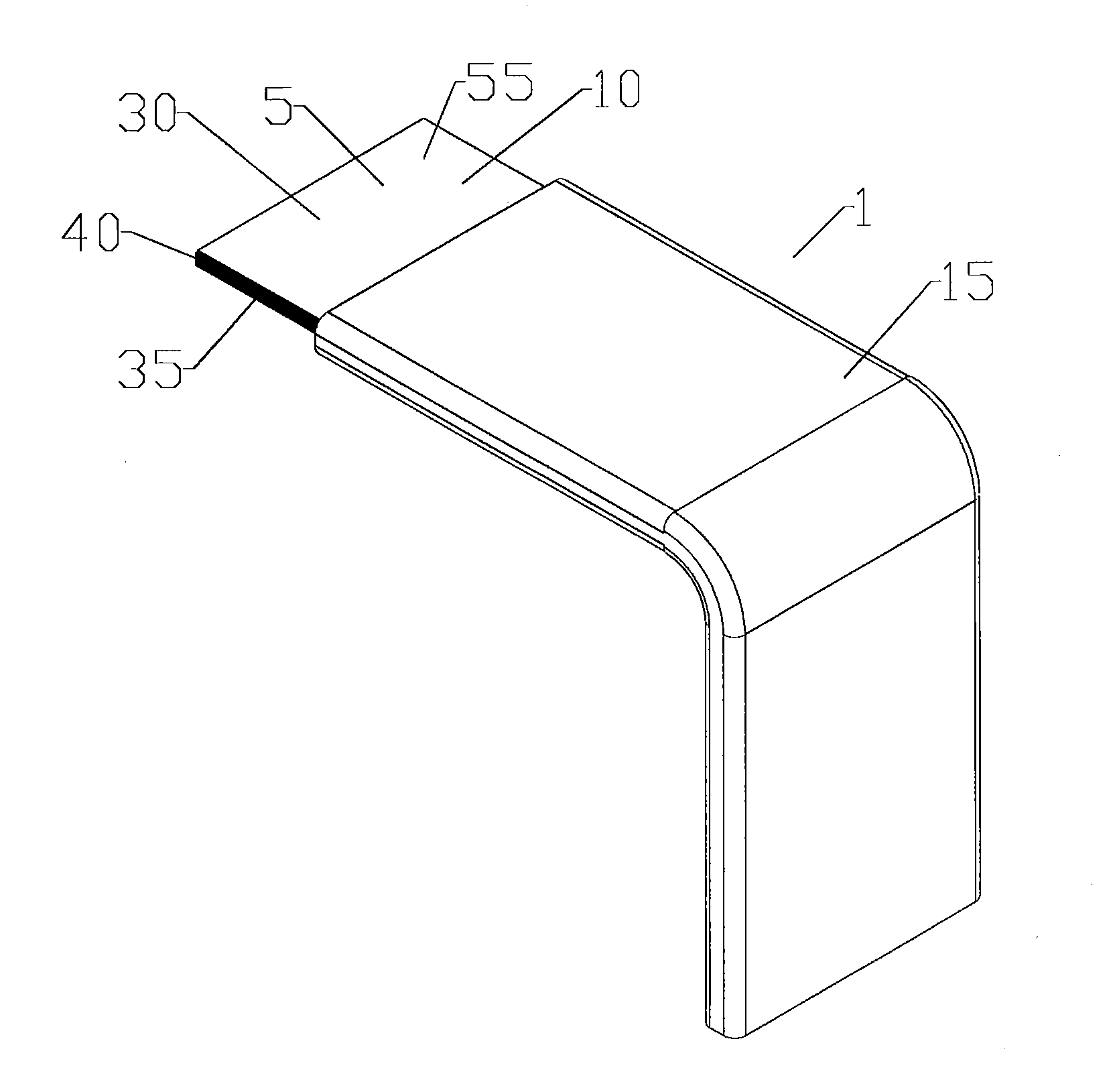
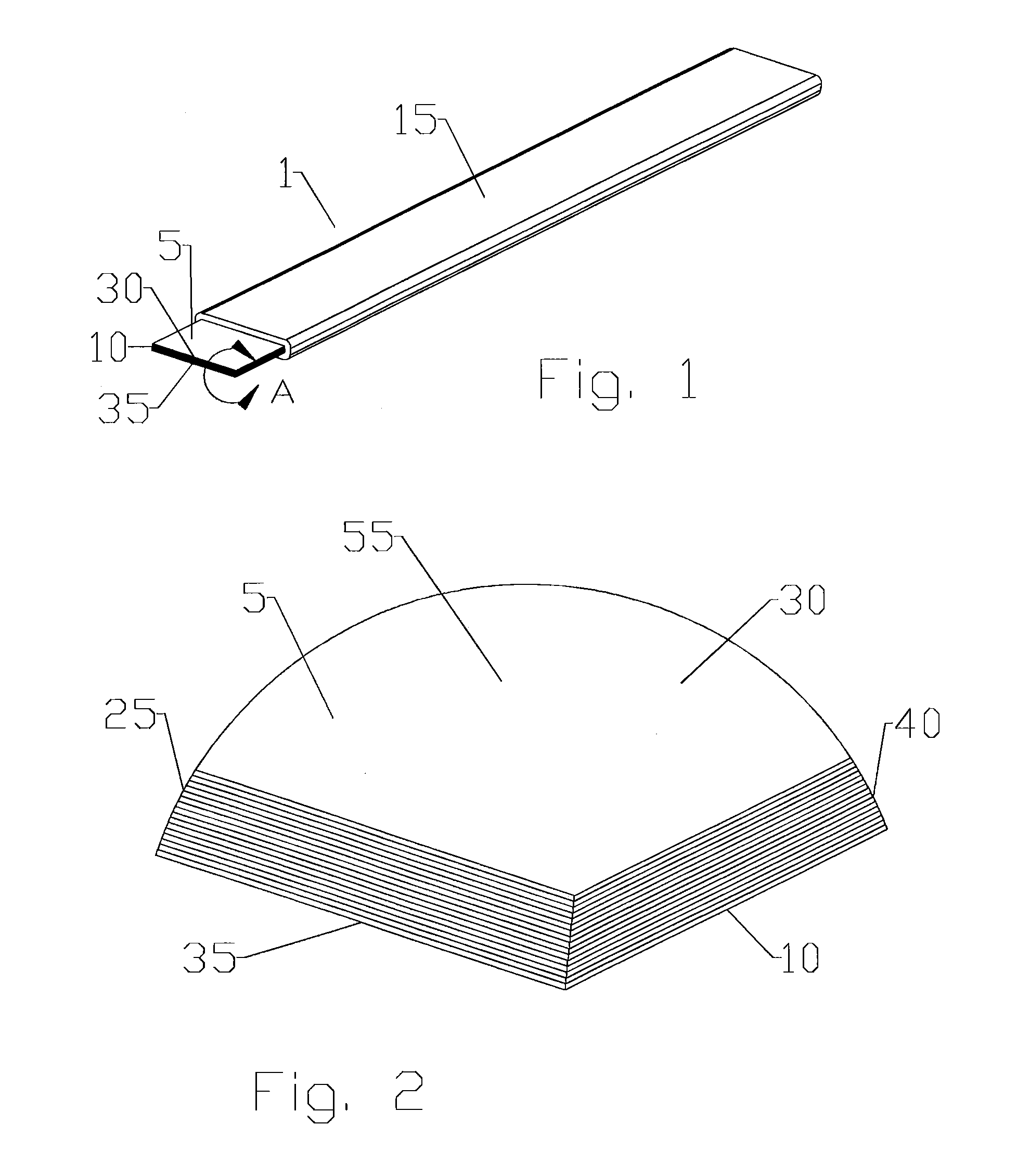
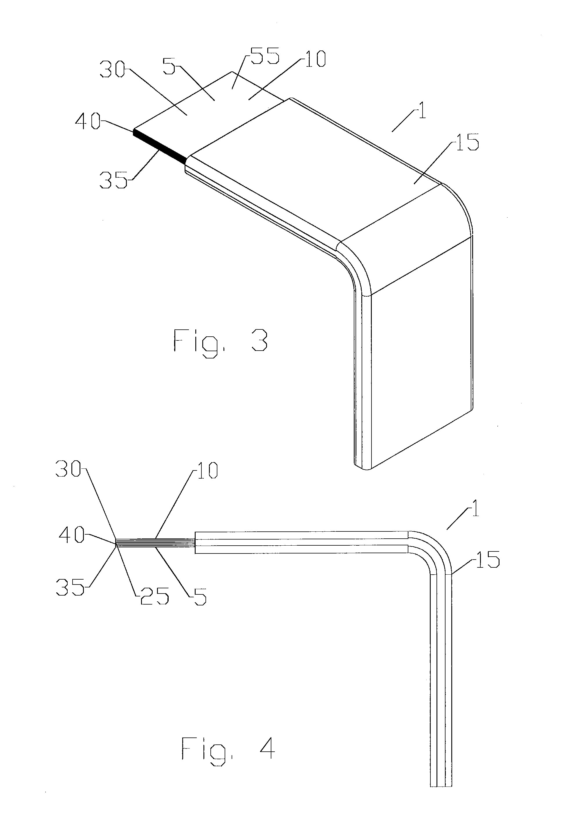
[0021]An exemplary flexible aluminum power cable 1 is demonstrated in FIGS. 1-5. As best shown in FIG. 2, the power cable 1 may be formed with a plurality of separate generally planar conductors 5 superposed in a stack 10, the stack 10 surrounded by a jacket 15. For example, a stack 10 of 16 layers of 0.005″ thick and 1″ wide aluminum conductors 5 provides a cable 1 with current characteristics generally equivalent to 1 / 0 AWG standard circular cross section insulated aluminum power cable.

[0022]The flattened characteristic of the cable 1 has inherent bend radius advantages. When the bending moment is applied across the narrow dimension of a rectangular conductor 1, the bending radius may be dramatically reduced. For ...


PUM

PropertyMeasurementUnit
frictional coefficientaaaaaaaaaa
electrical cableaaaaaaaaaa
thicknessaaaaaaaaaa

Abstract

An electrical cable has a plurality of generally rectangular cross-section conductors superposed in a stack, the stack surrounded by a polymer jacket. The stack may be provided with a lubrication layer provided between at least two of the conductors. Conductors of the stack may have a thickness that is greater proximate the middle of the stack than at the top and bottom of the stack and / or a width that is less at the top and the bottom than at the middle. Further stacks may also be provided parallel and coplanar with the first stack, also surrounded by the polymer jacket.

Description

RELATED APPLICATION[0001]The present application is a continuation of U.S. patent application Ser. No.13 / 561,115, filed Jul. 30, 2012, the disclosure of which is hereby incorporated herein in its entirety.BACKGROUND OF THE INVENTION[0002]RF transceivers have traditionally been located on the ground and RF signals transmitted to / received from antennas mounted atop radio towers interconnected with the RF transceivers by RF coaxial cables. A move towards remote radio head (RRH) installations, wherein the RF transceivers are themselves located atop radio towers proximate the antennas, has reduced the need for RF coaxial cables to transmit the RF signals between the transceiver and the antenna, but has also increased the demand for electrical power at the top of the radio tower.[0003]Traditional electrical power cables comprise large gauge copper conductors with a circular cross section. However, such power cables are heavy, difficult to bend and have a high material cost directly relate...

Claims


Application Information

Patent Timeline
Patent Type & Authority Applications(United States)
IPC IPC(8): H01B7/00H01B7/08H01B3/30H01B1/02H01B3/44
CPCH01B7/0009H01B1/023H01B7/08H01B3/307H01B3/447H01B3/443H01B7/0823H01B7/0018
Inventor HARWATH, FRANK A.
Owner COMMSCOPE TECH LLC
Why Eureka
Try Eureka