
Formic acid decomposition apparatus and formic acid decomposition method

a formic acid decomposition and formic acid technology, applied in the direction of soldering apparatus, separation process, manufacturing tools, etc., can solve the problems of deteriorating electrical and mechanical properties of the formed solder joint, small cavities (voids) in the solder bump, harmful effect, etc., to achieve the effect of improving the production efficiency of products accompanying the soldering process and estimating the time for the replacement of the catalys

Inactive Publication Date: 2016-08-04
ORIGIN ELECTRIC CO LTD
View PDF5 Cites 5 Cited by
  • Summary
  • Abstract
  • Description
  • Claims
  • Application Information

AI Technical Summary

Benefits of technology

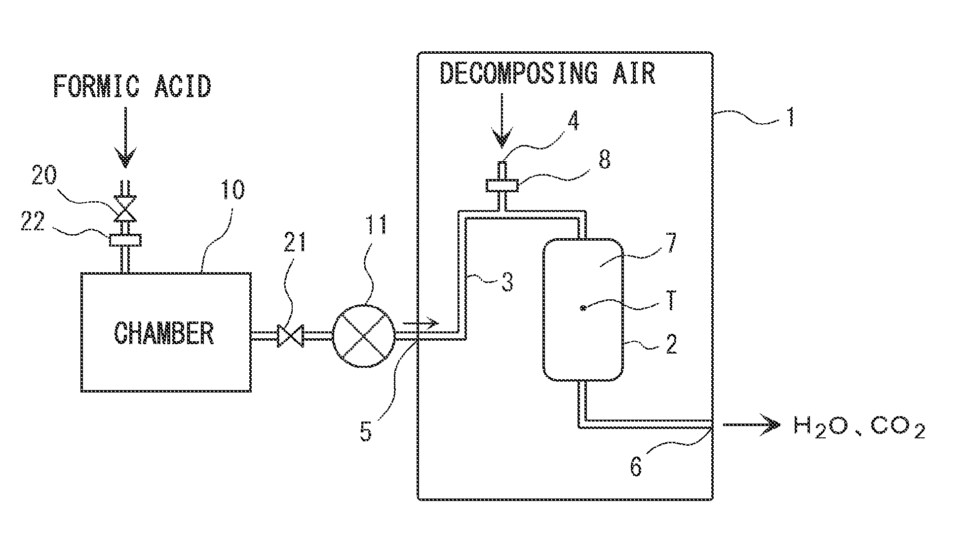
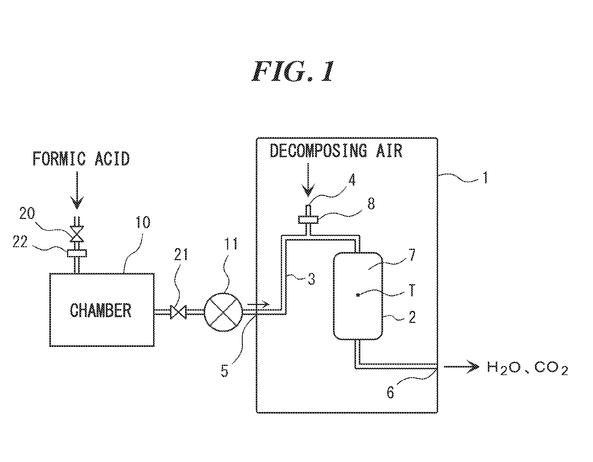
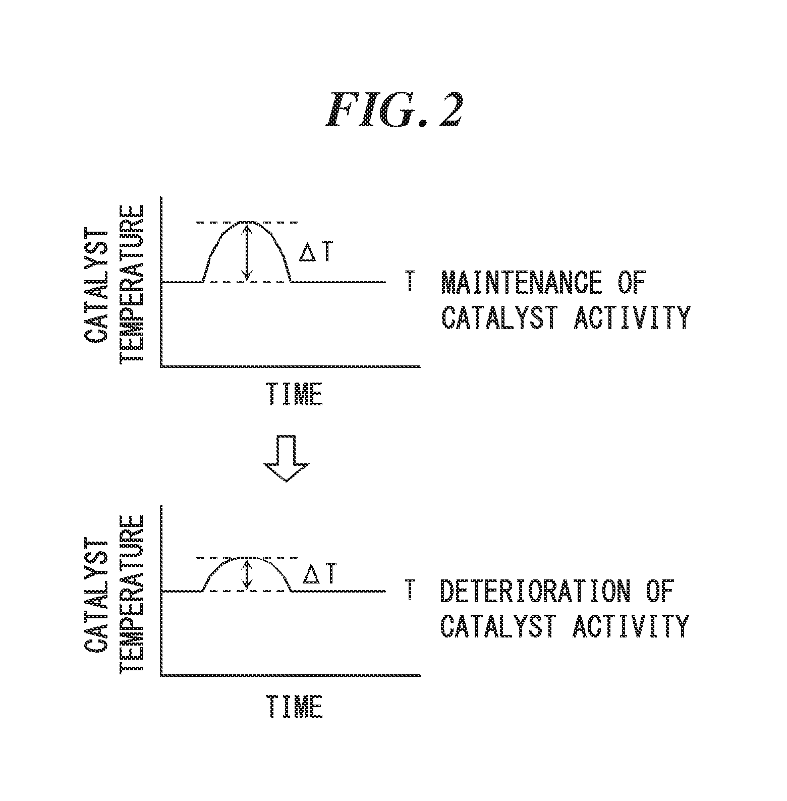
The present invention is a formic acid decomposition apparatus and method that can quickly break down formic acid into water and carbon dioxide. This is important for safely processing any remaining formic acid after a reduction process in a soldering apparatus. By heating the catalyst in the decomposition apparatus, formic acid can be effectively converted and water droplets can be prevented from remaining in the apparatus. The apparatus can also determine the degree of activity of the catalyst in real-time, allowing for improved production efficiency and estimation of the catalyst lifetime.

Problems solved by technology

However, according to a soldering process that uses a flux, small cavities (voids) may be formed in the solder bump due to decomposition of the flux.
These cavities not only deteriorate electrical and mechanical properties of a formed solder joint but also destroy flatness of a semiconductor with the solder bump and may generate a harmful effect on the following semiconductor joining process.
A volatile material of the decomposed flux may contaminate the inside of a reflow processor (soldering apparatus) and as a result a maintenance cost may increase.
In addition, a flux residue remains frequently on a semiconductor substrate to cause metal corrosion, and degradation of performance of an assembly.
However, formic acid sometimes corrodes a chamber material, a corrosion product may become a contamination source as a metallic foreign matter in the chamber, and fly and adhere to the substrate, electronic components mounted on the substrate and the like.
However, the apparatus is an apparatus that uses a reducing gas (hydrogen and carbon monoxide) generated by heating and decomposing formic acid and is not an apparatus that removes the oxide film with formic acid.

Method used


Image

  • Formic acid decomposition apparatus and formic acid decomposition method
  • Formic acid decomposition apparatus and formic acid decomposition method
  • Formic acid decomposition apparatus and formic acid decomposition method

Examples


example 1

[0082]As a catalyst, a Pt / alumina catalyst in which Pt is carried at 1.8 g / L on particulate alumina was used. A catalyst layer was prepared by filling 1 L of newly prepared catalyst in the formic acid decomposition part 2 and a test was performed according to the above-described test method (refers to as test (a)).

[0083]Next, 330 ml of a catalyst that is partially deactivated was prepared and filled in a portion of upper one third of the formic acid decomposition part 2 (in lower two thirds, the newly prepared catalyst that was used in the test (a) was filled), the test was performed according to the above-described test method (refers to as test (b)).

[0084]Further, 330 ml of a catalyst that is completely deactivated was prepared and filled in upper one third of the formic acid decomposition part 2 (in the lower two thirds, the newly prepared catalyst that was used in the test (a) was filled), and the test was performed according to the above-described test method (refers to as test...


PUM

PropertyMeasurementUnit
Temperatureaaaaaaaaaa
Volumetric flow rateaaaaaaaaaa

Abstract

To provide a formic acid decomposition apparatus and method, which can dispose of formic acid safely and quickly and determine the activity of a filled catalyst. The apparatus is for decomposing formic acid contained in exhaust gas exhausted from a soldering apparatus in which a surface oxide film is reduced with formic acid, into water and carbon dioxide. The apparatus has a formic acid decomposition part in which a formic acid decomposition catalyst is filled; a gas introduction pipe for introducing gas containing formic acid into the decomposition part; and a gas introduction unit for introducing oxygen or gas containing oxygen into the decomposition part. In the apparatus, the activity of the catalyst is determined on the basis of an amount of change of a catalyst temperature by heat generation during a decomposition reaction of formic acid. The method includes mixing exhaust gas containing formic acid exhausted from the soldering apparatus, and oxygen or gas containing oxygen such that a molar ratio of formic acid and oxygen (oxygen / formic acid) is 1.5 or more, and allowing the mixed gas to react in the presence of the catalyst to decompose formic acid into water and carbon dioxide.

Description

TECHNICAL FIELD[0001]The present invention relates to a formic acid decomposition apparatus and a formic acid decomposition method.BACKGROUND ART[0002]When a solder bump is formed on a semiconductor chip, a solder is deposited on a pad and then a shape of the solder bump is changed from a mush room shape to a hemisphere shape, followed by reflowing to join by soldering. According to a conventional soldering method, in order to form a uniform solder bump, a surface oxide film of a solder is removed with a flux to cleanse the surface of the solder bump.[0003]However, according to a soldering process that uses a flux, small cavities (voids) may be formed in the solder bump due to decomposition of the flux. These cavities not only deteriorate electrical and mechanical properties of a formed solder joint but also destroy flatness of a semiconductor with the solder bump and may generate a harmful effect on the following semiconductor joining process. A volatile material of the decomposed ...

Claims


Application Information

Patent Timeline
IPC IPC(8): B01D53/86B23K3/08
CPCB01D53/8668B01D53/8696B01D2251/11B01D2255/1021Y02P70/181B01D2257/70B23K3/08B01D2257/708B01D2255/2092
Inventor OZAWA, NAOTO
Owner ORIGIN ELECTRIC CO LTD
Learn More