
Projector

a projector and projector technology, applied in projectors, color television details, instruments, etc., can solve the problems of significant deformation of display quality, increased device size, and increased size of imaging lens or projection lens, so as to reduce speckle noise

Active Publication Date: 2016-08-04
SEIKO EPSON CORP
View PDF0 Cites 4 Cited by
  • Summary
  • Abstract
  • Description
  • Claims
  • Application Information

AI Technical Summary

Benefits of technology

The invention aims to address the issue of speckle noise in projectors without making the device larger. The technical effect is to provide a reliable solution to reduce speckle noise.

Problems solved by technology

Accordingly, display quality is significantly degraded.
As a result, according to the projection display device, there is a problem in that the device increases in size due to a need for a space where the pupil matching means is disposed and an increase in the size of the imaging lens or the projection lens.
For this reason, it is not possible to use the prediction method of Document 2 practically.
Specifically, when the value of EP is small, speckle noise is easily recognized, and when the value of EP is great, speckle noise is not easily recognized.

Method used


Image

  • Projector
  • Projector
  • Projector

Examples


first embodiment

[0068]Hereinafter, a first embodiment of the invention will be described referring to FIGS. 1 to 6.

[0069]In this embodiment, an example of a projector using a laser light source device is shown.

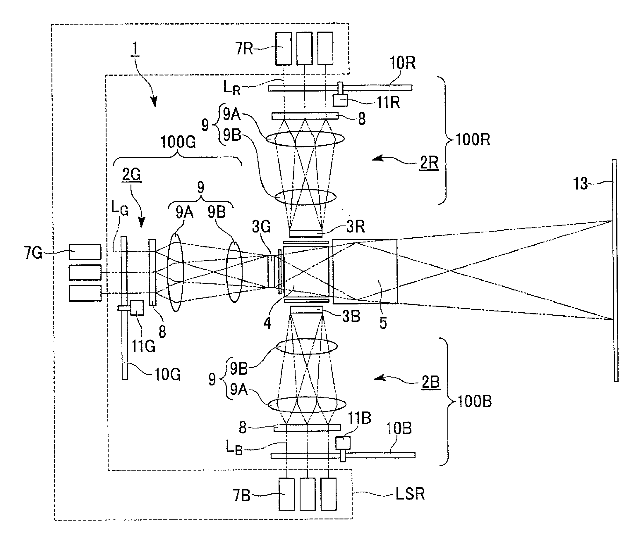
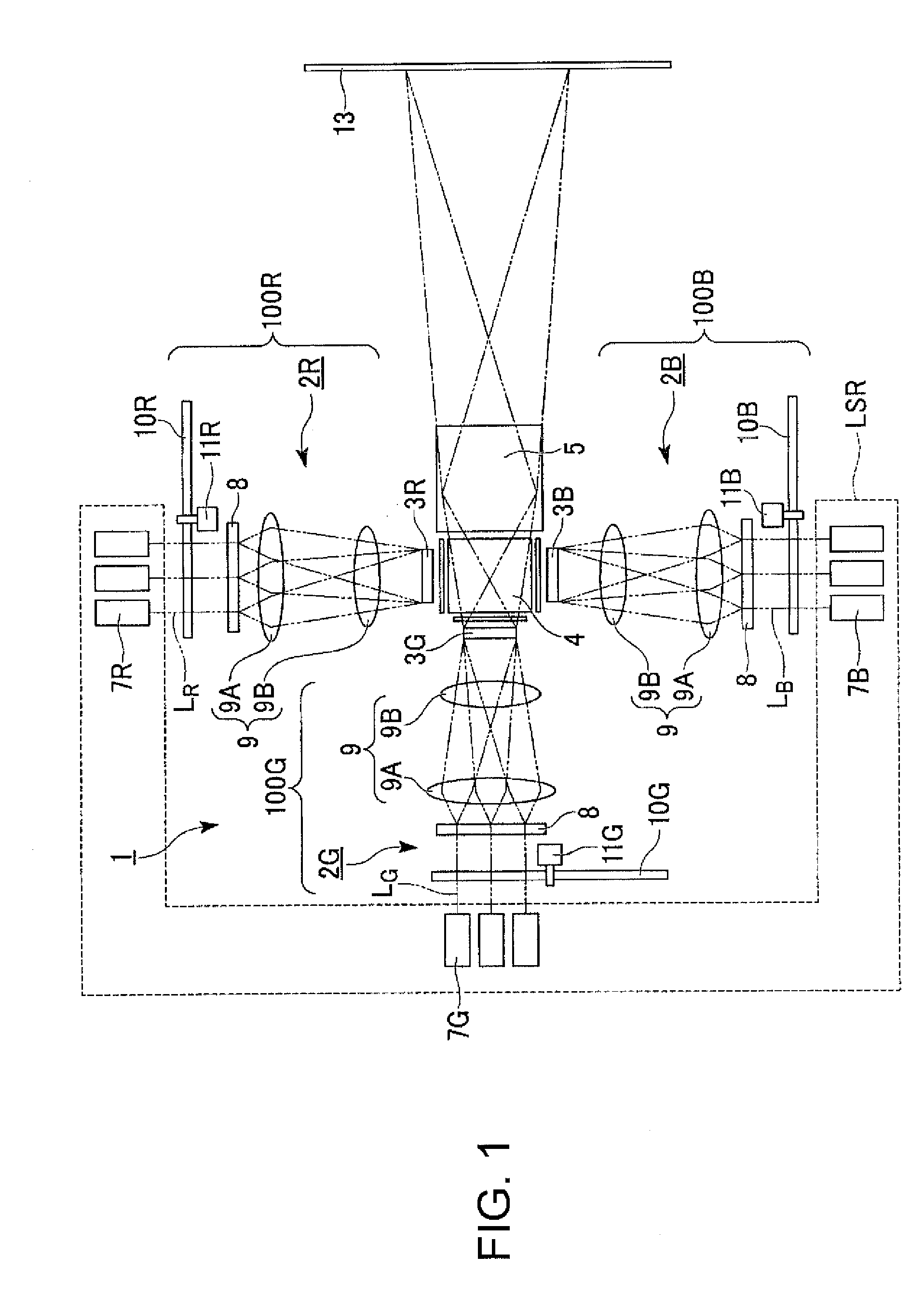
[0070]FIG. 1 is a schematic configuration diagram showing a projector according to the first embodiment of the invention.

[0071]In the following drawings, for ease of visual recognition of the respective constituent elements, the constituent elements may be different in scale.

[0072]As shown in FIG. 1, a projector 1 includes a laser light source device LSR, an illumination optical system 100R, an illumination optical system 100G, an illumination optical system 100B, a red liquid crystal light valve (first light modulation element) 3R, a green liquid crystal light valve (second light modulation element) 3G, a blue liquid crystal light valve (third light modulation element) 3B, a color composition element 4, and a projection optical system 5.

[0073]The laser light source device LSR includes at lea...

second embodiment

[0121]Hereinafter, a second embodiment of the invention will be described referring to FIGS. 11 and 12.

[0122]The basic configuration of a projector of the second embodiment is the same as the first embodiment, and the configuration of a light source device is different.

[0123]FIG. 11 is a schematic configuration diagram showing a projector according to the second embodiment of the invention.

[0124]In FIG. 11, the constituent elements common to FIG. 1 used in the first embodiment are represented by the same reference numerals, and detailed description thereof will not be repeated.

[0125]As shown in FIG. 11, a projector 21 includes a laser light source device LSR, an illumination optical system 200R, an illumination optical system 200G, an illumination optical system 200B, a red liquid crystal light valve 3R, a green liquid crystal light valve 3G, a blue liquid crystal light valve 3B, a color composition element 4, and a projection optical system 5.

[0126]The illumination optical system 2...


PUM


Abstract

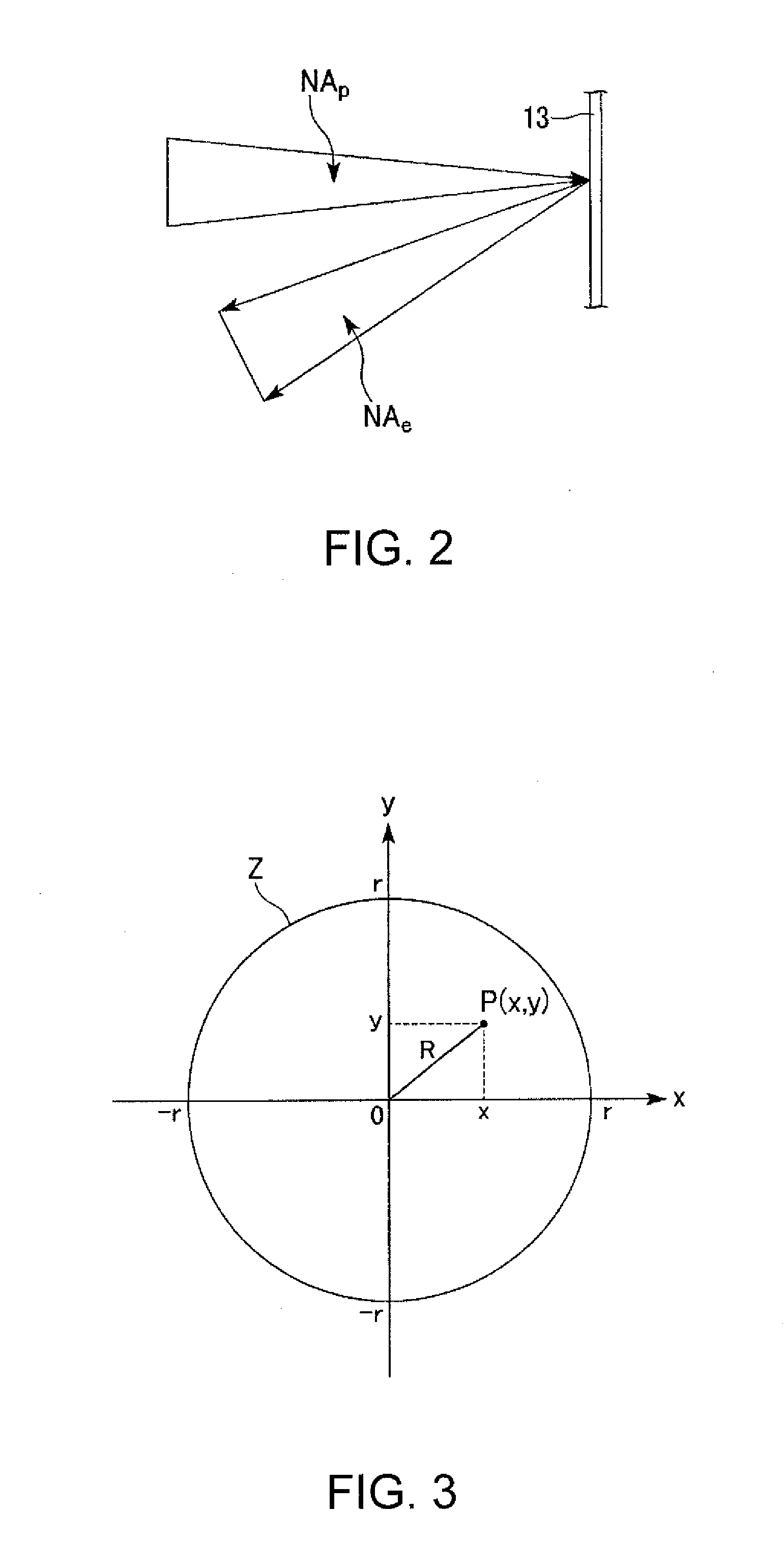
A projector capable of reliably reducing speckle noise includes a light modulation element which modulates laser light, and a projection optical system on which light emitted from the light modulation element is incident. When the center coordinates of an illumination distribution of laser light in an exit pupil of the projection optical system are x=0 and y=0, normalized illumination at each coordinate is P(x,y), and a calculation range of integration is r (mm), the value of EP determined from a specific numerical expression is set in a range according to the color of laser light.

Description

BACKGROUND[0001]1. Technical Field[0002]The present invention relates to a projector.[0003]2. Related Art[0004]A projector using a laser light source has advantages, such as reduction in the size of the device, excellent color reproducibility, instantaneous lighting, and long life time of the light source. In general, laser light emitted from the laser light source is coherent light. For this reason, in this type of projector, a spot pattern, called speckle noise, caused by interference of laser light may be visually recognized on a screen. Accordingly, display quality is significantly degraded.[0005]In the projector of the related art using the laser light source, a countermeasure for suppressing degradation of display quality due to speckle noise is used. JP-A-2009-216843 (Document 1) discloses a projection display device in which an entrance pupil image of a projection lens is greater than an exit pupil diameter of an illumination optical system, and which includes pupil matching...

Claims


Application Information

Patent Timeline
Patent Type & Authority Applications(United States)
IPC IPC(8): G03B21/14
CPCG02B27/48G03B21/2033G03B21/208G03B21/142H04N9/3152H04N9/3161H04N9/3105
Inventor EGAWA, AKIRAOKAMOTO, JUNICHI
Owner SEIKO EPSON CORP
Learn More