Anode and x-ray generating tube, x-ray generating apparatus, and radiography system that use the anode

a technology of anode and generating tube, which is applied in the direction of x-ray tube target material, x-ray tube target and convertor, etc., can solve the problems of cracking in the conductive layer, difficulty in keeping the x-ray dose steady, so as to achieve stable x-ray dose, stable x-ray dose, and high reliability

Active Publication Date: 2016-08-04
CANON KK
View PDF2 Cites 4 Cited by
  • Summary
  • Abstract
  • Description
  • Claims
  • Application Information

AI Technical Summary

Benefits of technology

[0006]An object of the present invention is to provide an anode capable of keeping the X-ray dose steady in an X-ray generating tube by preventing a crack in a conductive layer that electrically connects a target layer and an anode member. Another object of the present invention is to provide a highly reliable X-ray generating apparatus and radiography system by building an X-ray generating tube that is stable in X-ray dose with the use of the anode.

Problems solved by technology

If the electrons that collide with the target layer stay in the target layer, the lingering electrons may invite the destabilization of the electron beam trajectory and a drop of the withstand voltage in the X-ray generating tube, which are known as phenomena observed at the time of charging up and in some cases make it difficult to keep the X-ray dose steady.
The repeated rises / drops in temperature at the end portion therefore causes the concentration of stress and the easing of stress repeatedly on bonding boundaries where the conductive layer is bonded to other members, and may result in a crack in the conductive layer, which is a thin film.
When a crack is formed in the conductive layer, the conductivity of the conductive layer drops, and the resultant destabilization of a prescribed anode potential and lingering of electrons in the target layer can present difficulties in keeping the X-ray dose steady.

Method used


Image

  • Anode and x-ray generating tube, x-ray generating apparatus, and radiography system that use the anode
  • Anode and x-ray generating tube, x-ray generating apparatus, and radiography system that use the anode
  • Anode and x-ray generating tube, x-ray generating apparatus, and radiography system that use the anode

Examples


example 1

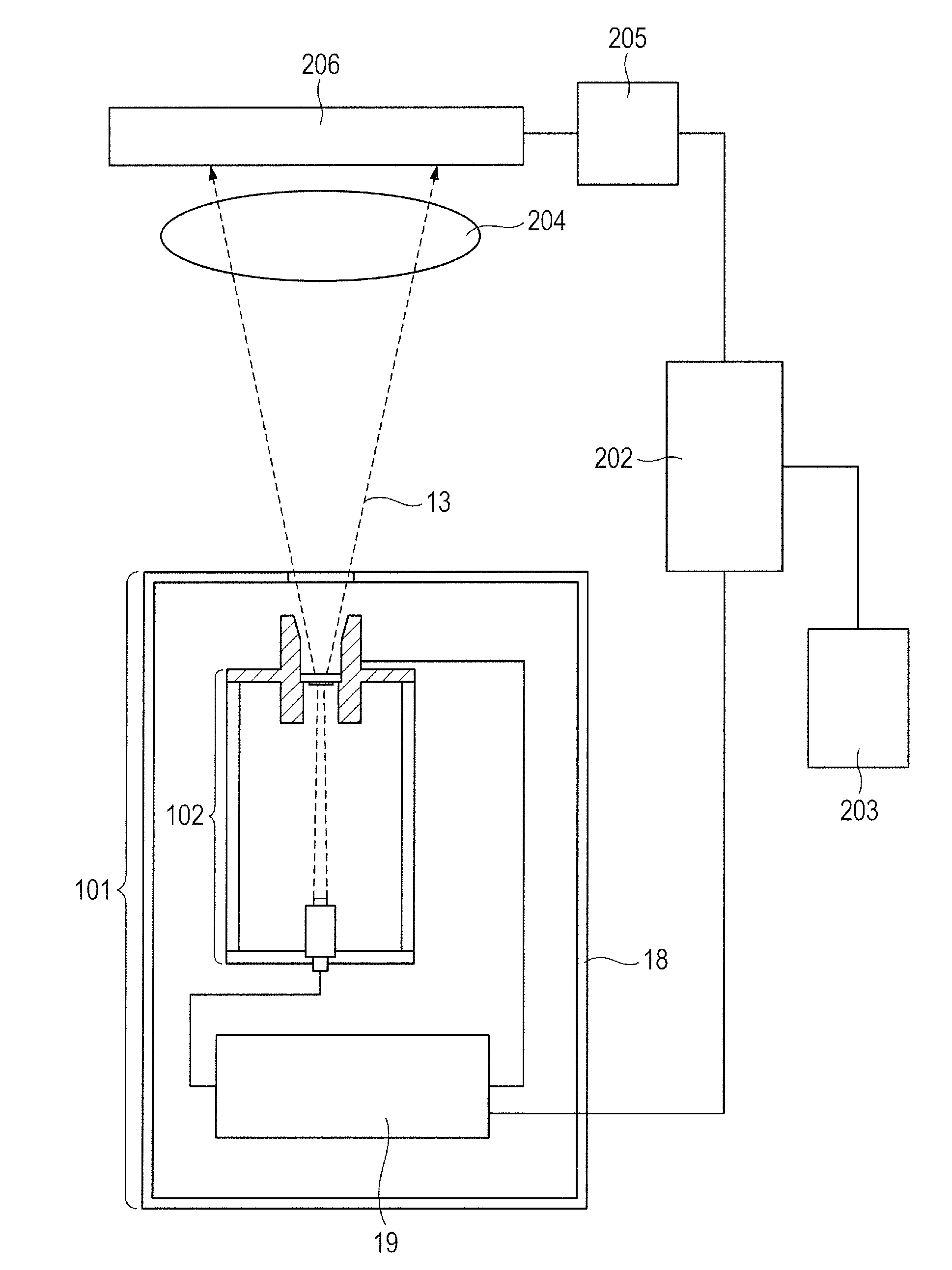
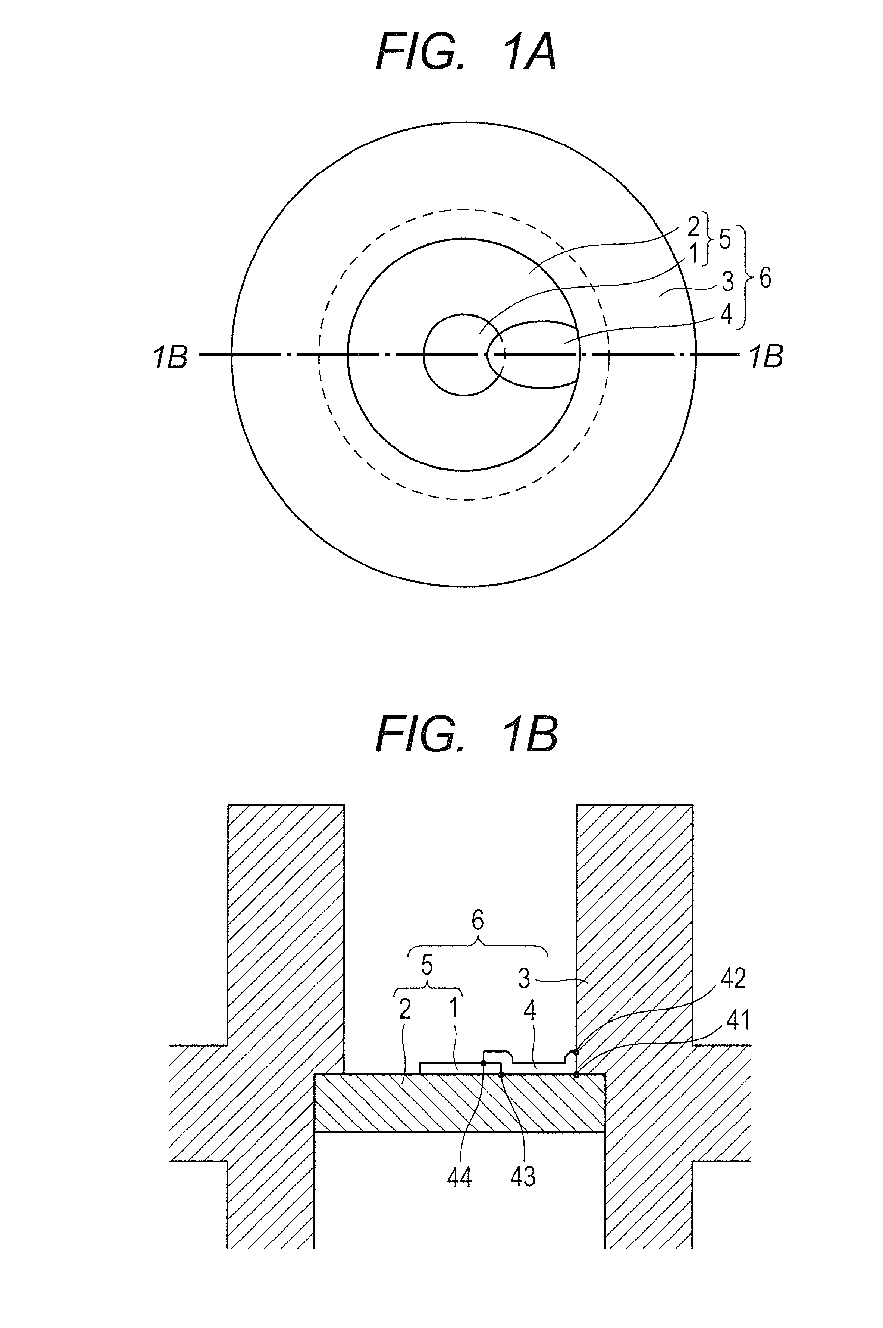
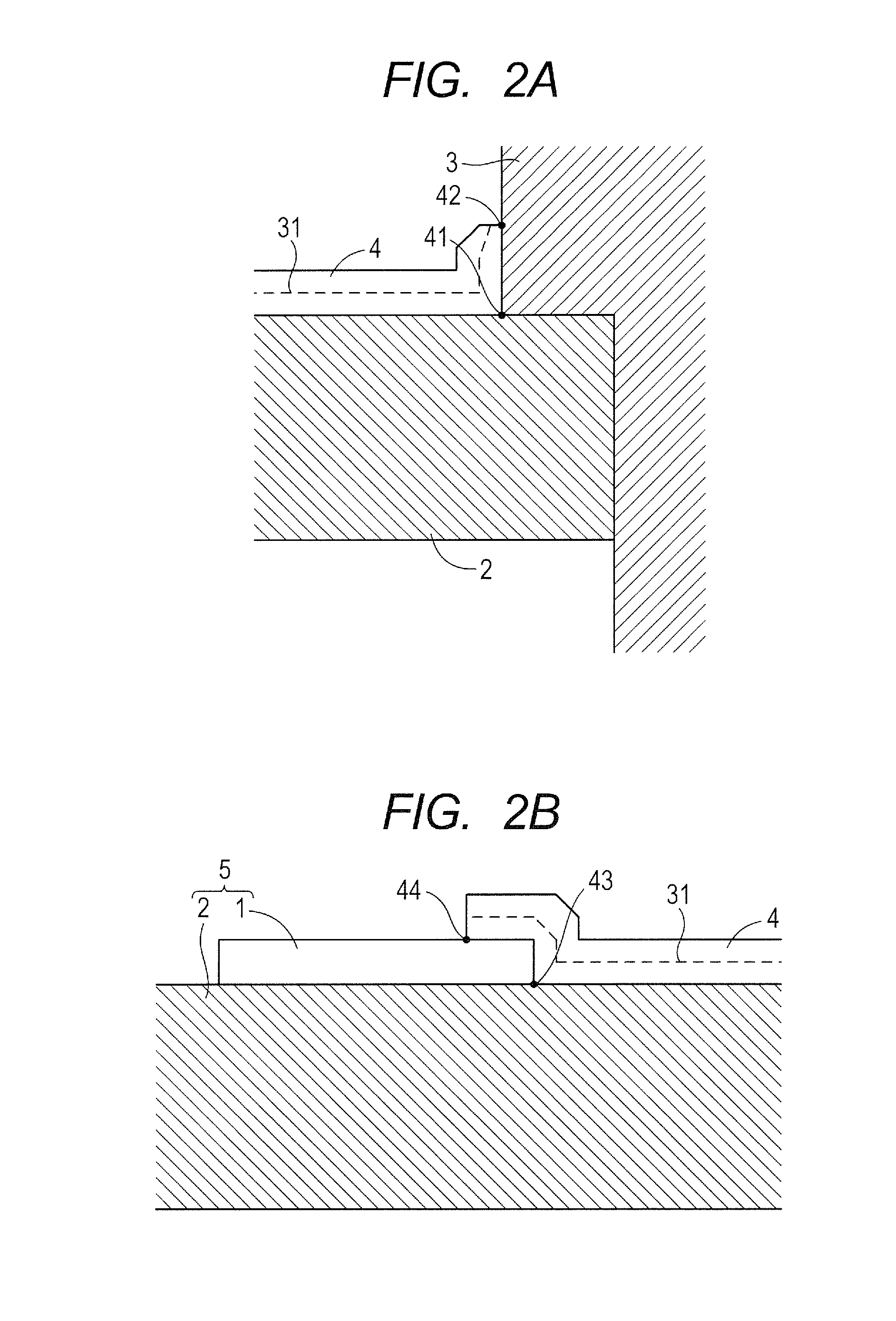
[0058]In Example 1, an X-ray generating tube that used the anode 6 of FIG. 1A and FIG. 1B was manufactured, and the X-ray generating apparatus 101 including this X-ray generating tube was further manufactured.

[0059]Sumicrystal, which is a synthetic diamond product of Sumitomo Electric Industries, Ltd. and has a diameter of 5 mm and a thickness of 2 mm, was first used for the supporting substrate 2. A metal under layer (not shown) was formed by performing metallizing processing on the side surface 2 of the supporting substrate 2 with the use of a paste containing Ti. Next, the target layer 1 was formed by sputtering tungsten to a thickness of 6 μm for a 3-mm diameter range on a central portion of one surface of the supporting substrate 2. To form this target layer 1, argon gas was used as the carrier gas and a sintered body of tungsten was used as the sputtering target. The supporting substrate 2 on which the target layer 1 had been formed was put inside the anode member 3 made of tu...

example 2

[0065]An X-ray generating tube and an X-ray generating apparatus were fabricated and evaluated the same way as in Example 1, except that the anode member 3 of FIG. 3A and FIG. 3B having the electron beam passage widening toward the electron emitting portion was used. The anode 6 used in Example 2 is improved in the reliability of electrical connection because the electron beam passage of the anode member 3 opens wider outward in the tube radial direction, which makes the area of contact between the anode member 3 and the connecting electrode layer 4 large. In Example 2 also, there was no problem with regards to static withstand voltage and stable driving was accomplished. Radiographic images having no shot-to-shot fluctuations in shooting quality and having a high SN ratio were obtained as a result.

[0066]The anode 6 was dismantled after the drive evaluation to observe the target 5. The observation revealed no cracks in the connecting electrode layer 4 and the target layer 1 and no g...


PUM


Abstract

Provided is an anode capable of keeping the X-ray dose steady in an X-ray generating tube by preventing a crack in a connecting electrode layer, which electrically connects a target layer and an anode member. The anode includes a first bonding boundary where the connecting electrode layer, which electrically connects the target layer and the anode member, is bonded to a supporting substrate of a target, and a second bonding boundary where the connecting electrode layer is bonded to the anode member in which the connecting electrode layer is formed so that the first bonding boundary and the second bonding boundary are on the same side with respect to the connecting electrode layer.

Description

BACKGROUND OF THE INVENTION[0001]1. Field of the Invention[0002]The present invention relates to a radiography system applicable to medical equipment, nondestructive testing apparatus, and the like, an X-ray generating apparatus for use in the system, and an X-ray generating tube for use in the apparatus, and more particularly, to an anode thereof.[0003]2. Description of the Related Art[0004]In an imaging system using an X-ray, in general, an X-ray generating tube is configured to control the trajectory of electrons emitted from a cathode such as a filament with the use of a control electrode, and then accelerate the electrons toward an anode to which an electric potential higher than that of the cathode is applied. The accelerated electrons collide with a target layer formed in the anode, thereby generating an X-ray. The generated X-ray is emitted to the outside of the X-ray generating tube through a transmitting window to irradiate an irradiation object, and the X-ray transmitted ...

Claims


Application Information

Patent Timeline
Patent Type & Authority Applications(United States)
IPC IPC(8): H01J35/08H01J35/06H05G1/30H01J35/16
CPCH01J35/08H01J35/16H01J2235/081H05G1/30H01J35/06H01J35/116H01J35/186H01J2235/083
Inventor YANAGISAWA, YOSHIHIROYAMADA, SHUJIOGURA, TAKAOITO, NOBUHIRO
Owner CANON KK
Why Eureka
Try Eureka