
Power supply system and method for a movable vehicle within a structure

Active Publication Date: 2016-08-11
HYPERLOOP TECH INC
View PDF4 Cites 13 Cited by
  • Summary
  • Abstract
  • Description
  • Claims
  • Application Information

AI Technical Summary

Benefits of technology

The patent is about a high-speed transportation system that uses a low pressure environment to reduce drag and energy costs. The vehicles operating in the system require an onboard power supply, which can come from an energy storage device or an external source. The patent describes a solution that utilizes microwaves to power the vehicles without physical contact between them and the external source. The microwaves are injected into a tube, where the vehicle travels, and the energy is converted into electrical current to power the onboard systems. This technology allows for longer distances and greater potential vehicle speeds while reducing energy costs.

Problems solved by technology

However, as these attempts have been in the context of open air transmission, these systems suffer from signal dispersion with distance.
Electromagnetic propulsion, which requires a power supply and on-board energy storage in batteries, results in increased vehicle mass.
However, such an on-board VFD will also likely be quite heavy and increase the mass of the vehicle.

Method used


Image

  • Power supply system and method for a movable vehicle within a structure
  • Power supply system and method for a movable vehicle within a structure
  • Power supply system and method for a movable vehicle within a structure

Examples


Embodiment Construction

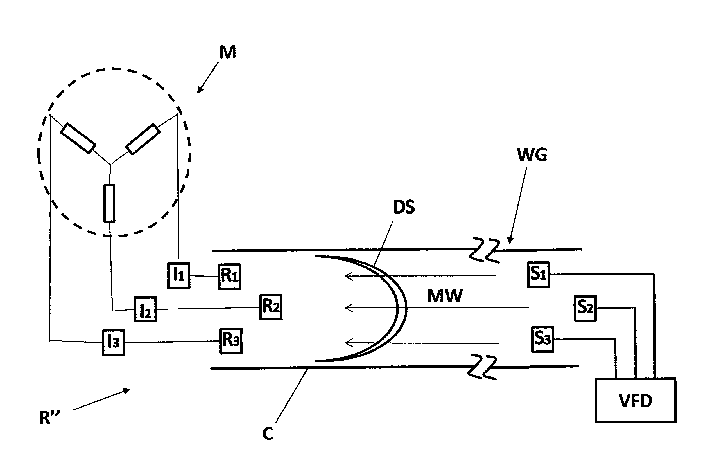
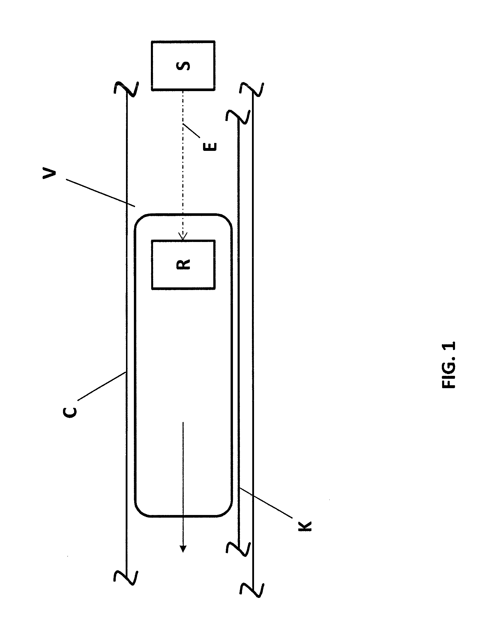
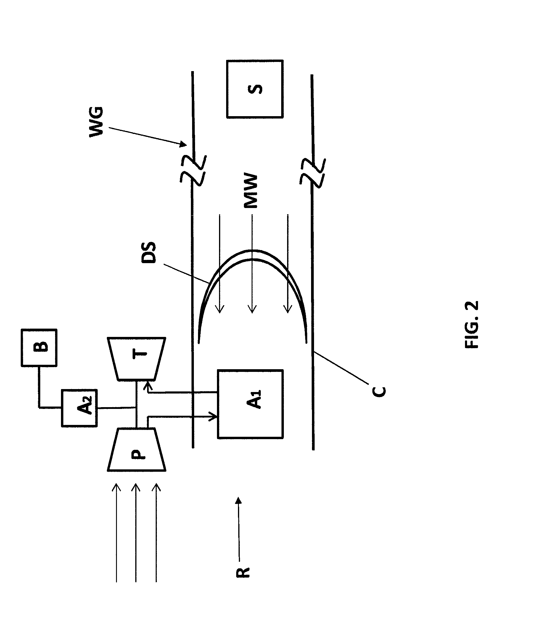
[0009]In a high speed, high efficiency transportation system, a low pressure environment can be utilized in order to reduce drag on a vehicle at high operating speeds. In this manner, the transportation system achieves the benefit of allowing a greater potential vehicle speed while lowering energy costs associated with overcoming drag forces. Preferably, these systems use a near vacuum within a tubular structure and the vehicles operating within the tube require an onboard power supply for running systems such as life support, controls, compressor, and / or propulsion. Preferably, the power can come from an energy storage device located in or on the vehicle, such as a battery, or from an external source.

[0010]In a high speed scenario, because physical contact between a vehicle transported at a velocity of up to and in excess of 300 m / s and a stationary object may be undesirable because of the associated drag and rapid wear of contact surfaces, it would be advantageous to achieve an ex...


PUM


Abstract

A power supply system and method for a vehicle movable within a structure is provided. The power supply system includes at least one energy source arranged at a fixed location within the structure to transmit energy within the structure, and a receiver, arranged on the vehicle to receive the energy transmitted from the energy source, being configured to convert the energy to electrical power and / or thrust.

Description

CROSS-REFERENCE TO RELATED APPLICATIONS[0001]The present application is a Non-provisional application claiming the benefit of U.S. Provisional Application No. 62 / 243,903 filed Oct. 20, 2015 and claiming the benefit of U.S. Provisional Application No. 62 / 113,511 filed Feb. 8, 2015, the disclosures of which are expressly incorporated by reference herein in their entireties.BACKGROUND OF THE INVENTION[0002]1. Field of the Invention[0003]The present invention relates to a power supply system for a transport vehicle. In particular, the power supply system can be used to supply power to running systems such as life support, controls, compressor, and / or propulsion.[0004]2. Discussion of Background Information[0005]Moving vehicles in transportation systems, e.g., railway or bus systems, can use an onboard power supply for running systems such as controls, compressor, and / or propulsion. The power can come from an energy storage device located in or on the vehicle, such as a battery. However,...

Claims


Application Information

Patent Timeline
IPC IPC(8): B60L11/00
CPCB60L11/002B60L50/53B60L50/90Y02T10/70
Inventor FINODEYEV, FILIPGIEGEL, JOSHUABAMBROGAN, BROGANO'NEAL, GEORGEHOSSEINI, KAVEH
Owner HYPERLOOP TECH INC
Learn More