Cabin Pressure Outflow Valve Noise Suppression Devices and Methods

a technology of noise suppression device and cabin pressure, which is applied in the direction of energy-saving board measures, mechanical equipment, transportation and packaging, etc., can solve the problems of inability to use oxygen mask systems, and inability to meet the needs of people at these altitudes, so as to reduce cabin noise and improve flow efficiency

Active Publication Date: 2016-08-11
THE BOEING CO
View PDF14 Cites 12 Cited by
  • Summary
  • Abstract
  • Description
  • Claims
  • Application Information

AI Technical Summary

Benefits of technology

[0010]Embodiments of the present disclosure relate to a Cabin Pressure Outflow Valve (CPOV) having retractable aerodynamic features configured to reduce cabin noise and improve flow efficiency, among other things.

Problems solved by technology

And, while flying at this altitude increases efficiencies, it also requires that some technical difficulties to be overcome.
One of these difficulties is that the air at these altitudes does not contain enough oxygen to sustain human life.
In large commercial aircraft, however, oxygen mask systems are impractical due to, for example, the number of passengers, size and space requirements, and the need for passengers and flight attendants to be able to move about the cabin.
However, this can result in flow separation, which can result in tonal noise.
At low differential pressures, the tonal noise can propagate into the airplane cabin.
These fixed aerodynamic devices, however, can produce additional broadband noise at lower and higher differential pressures (e.g., during the full flight regime) and also represent a possible flow inefficiency through the CPOV.
As a result, while these devices are deployed at all times (i.e., because they are molded into the gate, for example), they are only needed in fairly limited conditions (i.e., only during fairly small portions of the flight regime).
The tonal noise at lower differential pressures, for example, is transitory; yet, the fixed aerodynamic devices can result in increased broadband noise even when no tonal noise is present.

Method used


Image

  • Cabin Pressure Outflow Valve Noise Suppression Devices and Methods
  • Cabin Pressure Outflow Valve Noise Suppression Devices and Methods
  • Cabin Pressure Outflow Valve Noise Suppression Devices and Methods

Examples


Embodiment Construction

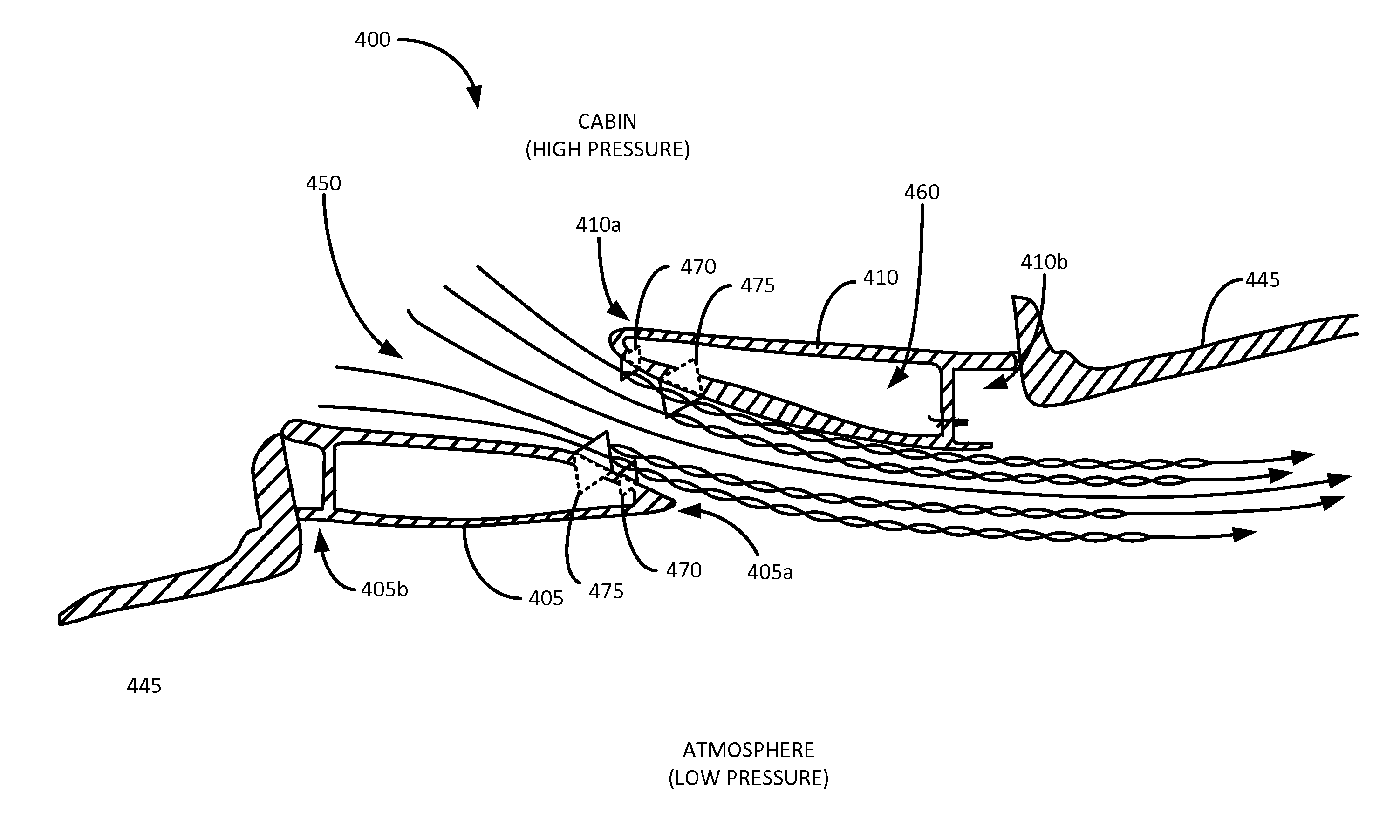
[0026]Embodiments of the present disclosure relate generally to Cabin Pressure Outflow Valves (CPOVs), and more particularly to a system and method for use with CPOVs utilizing moveable flow disruptors configured to reduce noise and improve flow efficiency therethrough. In some embodiments, the system can comprise a CPOV with one or more aerodynamic features, or flow disruptors, to reduce separation of the flow through the valve. The system can comprise, for example, one or more fixed aerodynamic surfaces and / or one or more moveable aerodynamic surfaces to attenuate tonal noise. One or more of these aerodynamic surfaces can be moveable, or retractable, to reduce broadband noise, which can be caused by flow across the flow disruptors themselves, among other things.

[0027]To simplify and clarify explanation, the disclosure is described herein as a CPOV. One skilled in the art will recognize, however, that the disclosure is not so limited. The system can be used, for example and not lim...


PUM


Abstract

A system and method for regulating pressure inside a vehicle (“cabin pressure”) with reduced noise is disclosed. The system can include a forward gate and an aft gate that can be moved from a closed position to an open position to release cabin pressure in a controlled manner. The forward gate and the aft gate can comprise one or more flow disruptors. A first portion of the flow disruptors can be fixed and a second portion can be moveable between a retracted position and a deployed in position. In the retracted position the one or more flow disruptors can reduce broadband noise through the system by smoothing air flow therethrough. In the second position, the one or more flow disruptors can create boundary layer turbulence. The boundary layer turbulence can prevent, or delay, flow separation reducing tonal noises therethrough. In this manner, flow efficiency can be increased and noise reduced.

Description

FIELD[0001]Embodiments of the present disclosure relate generally to cabin pressure outflow valves and specifically to improved cabin pressure outflow valves for aircraft utilizing fixed and / or moveable aerodynamic elements for the reduction, or elimination, of tonal and / or broadband noise.BACKGROUND[0002]Commercial aircraft fly at very high altitudes. This is because, at least in part, the relatively thinner air at higher altitudes reduces drag. As a result, modern commercial aircraft fly in the range of approximately 30,000-45,000 feet above sea level (ASL), while private jets may fly as high as approximately 51,000 feet ASL. And, while flying at this altitude increases efficiencies, it also requires that some technical difficulties to be overcome.[0003]One of these difficulties is that the air at these altitudes does not contain enough oxygen to sustain human life. At altitudes above approximately 12,000-14,000 feet ASL, most humans begin to suffer from altitude induced hypoxia. ...

Claims


Application Information

Patent Timeline
Patent Type & Authority Applications(United States)
IPC IPC(8): B64D13/02F16K1/36B60H1/00F16K1/20
CPCB64D13/02F16K1/2021B60H2001/006B60H1/00757F16K1/36B60H1/00564B60H1/00871B60H1/248F16K1/2014F16K47/045Y02T50/50
Inventor LOUKUSA, STEVEN M.
Owner THE BOEING CO
Why Eureka
Try Eureka