Exhaust treatment apparatus and method

a technology of exhaust treatment and exhaust system, which is applied in the direction of exhaust treatment, mechanical equipment, engine components, etc., can solve the problems of increasing the thermal inertia affecting the operation of the exhaust system, and reducing the operation temperature of the catalyst, so as to reduce the catalyst light-off time, facilitate evaporation and mixing through the turbocharger, and facilitate the coupling of downstream aftertreatment devices

Inactive Publication Date: 2016-08-11
JAGUAR LAND ROVER LTD
View PDF8 Cites 4 Cited by
  • Summary
  • Abstract
  • Description
  • Claims
  • Application Information

AI Technical Summary

Benefits of technology

[0014]At least in certain embodiments, the light-off time of the catalyst can be reduced since it is disposed upstream of the turbocharger. The reductant and exhaust gases flow through the turbocharger together and this can promote evaporation and mixing through the turbocharger. The reductant can be introduced at an earlier point in time from cold start or at lower vehicle speeds. The reductant can, for example, be urea which can operatively be introduced into the flow of exhaust gases in an aqueous liquid form.
[0036]In another embodiment a recess may be formed in the substrate substantially coincident with said injection nozzle. Introducing the reductant into the substrate may promote evaporation and mixing of the reductant, which may prevent droplets of liquid from impacting on the turbocharger.

Problems solved by technology

A further problem arises when the diesel engine is turbocharged to improve performance.
This results in increased thermal inertia of the exhaust system upstream of the DOC along with increased heat extraction.
These factors can further delay achieving the light-off temperature of the catalyst.
A further limit on operating temperature arises with urea selective catalytic reduction systems (uSCR) for aftertreatment of nitrogen oxides.
This temperature limit is typically 180° C., but this may not be achieved during certain driving conditions, for example when the vehicle is driven in a city.
Under these operating conditions, the operation of the uSCR system may be restricted due to low diesel exhaust gas temperatures.
The recirculation of exhaust gases to the engine to reduce emission of nitrogen oxides, so called high-pressure exhaust gas recircuation (HP-EGR), can also present problems.
The exhaust gases are recirculated from the exhaust manifold to the engine intake manifold, but hydrocarbons and particulates in the exhaust gases can cause contamination and potential durability issues within the engine.
Finally, the packaging of diesel emissions aftertreatment systems, typically including oxidation catalysts (DOC), catalysed diesel particulate filters (cDPF) and uSCR, remains a constant challenge.
Current pre-turbocharger catalysts and exhaust gas recirculation catalysts tend to be limited in size due to use of conventional honeycomb structures.
The catalysts therefore require additional space and thus may only operate at low speed / load conditions and require an additional post-turbocharger conventional DOC.

Method used


Image

  • Exhaust treatment apparatus and method
  • Exhaust treatment apparatus and method
  • Exhaust treatment apparatus and method

Examples


Embodiment Construction

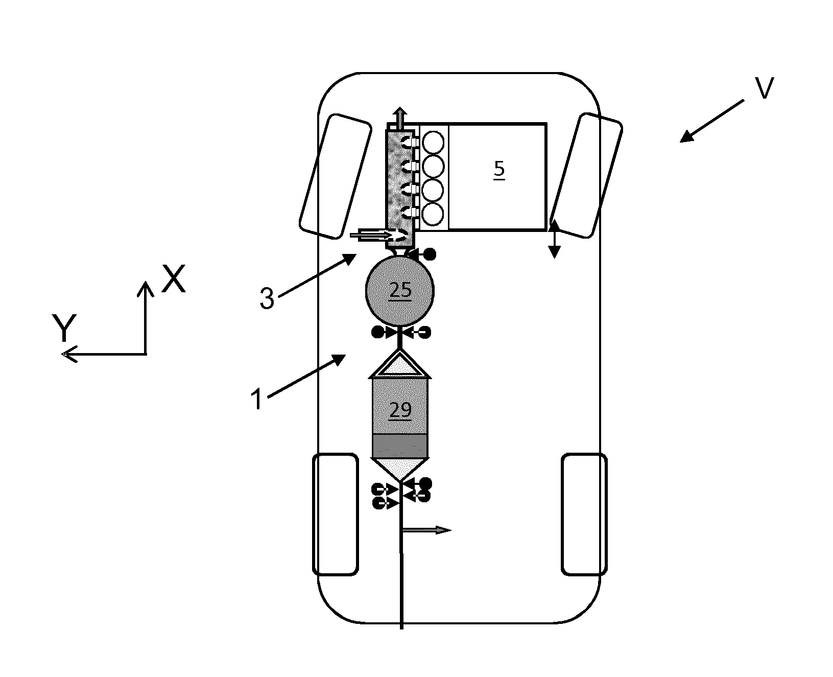
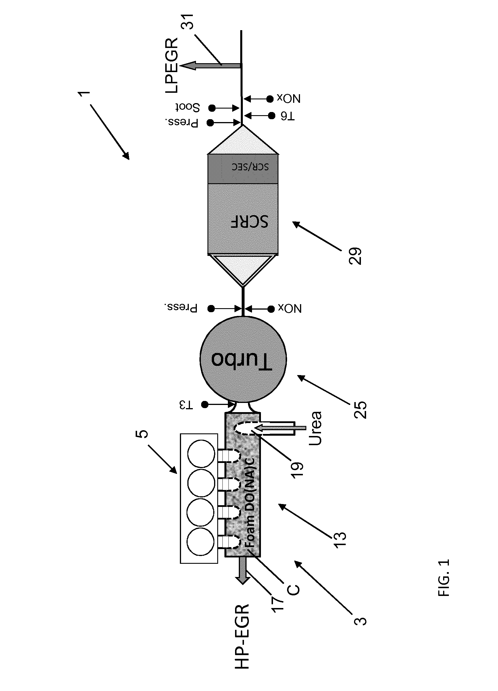
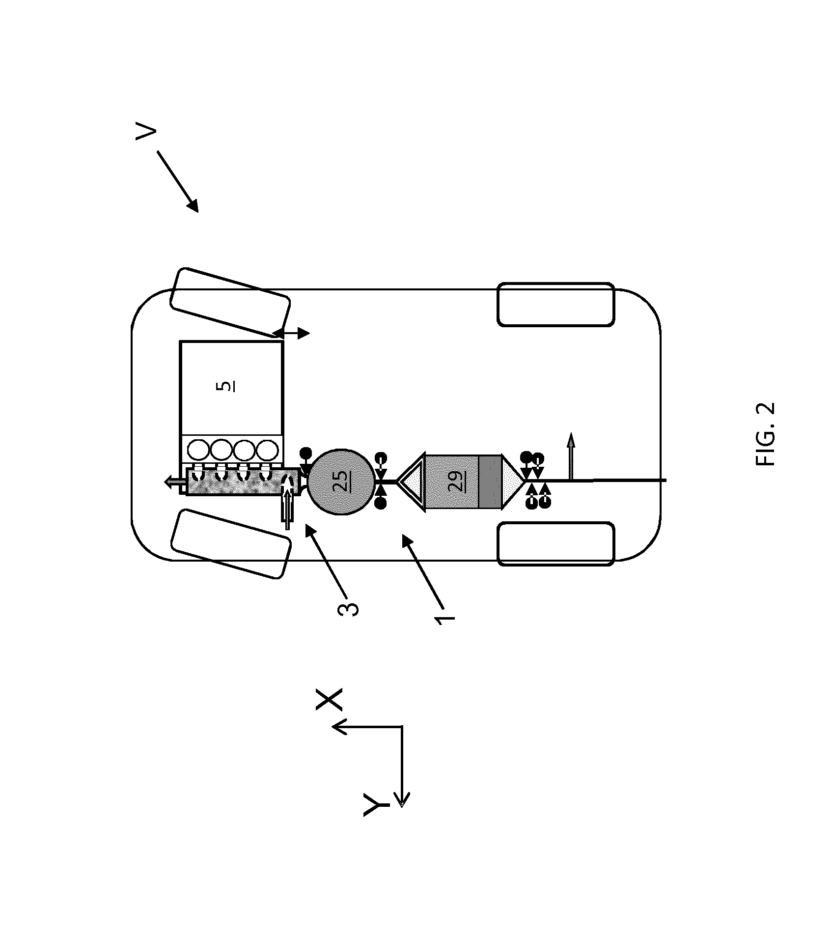
[0066]A schematic representation of an exhaust aftertreatment apparatus 1 incorporating a pre-turbocharger diesel oxidation catalyst (DOC) 3 in accordance with an embodiment of the present invention is shown in FIG. 1. The DOC 3 according to the present invention is intended for use in an automotive vehicle V having a compression-ignition (diesel) engine 5, as shown schematically in FIG. 2. A cylinder head 7 of the engine 5 is shown schematically in FIG. 3.

[0067]The engine 5 in the present embodiment comprises four (4) cylinders 9A-D each having an exhaust outlet (not shown). The exhaust outlets are coupled to respective exhaust gas inlets 11A-D of an exhaust manifold 13 by conduits 15A-D. The exhaust gas inlets 11A-D open into a catalyst chamber C defined by the exhaust manifold 13. The exhaust manifold 13 also comprises a high pressure return line 17, a reductant injection nozzle 19 and an outlet port 21. The high-pressure return line 17 recirculates high-pressure exhaust gases to...


PUM


Abstract

The present invention relates to an exhaust treatment apparatus (1) for an internal combustion engine (5). The apparatus includes a catalyst chamber (15) containing a catalyst (35). One or more exhaust gas inlets (11 A-D) are provided for supplying exhaust gases from the internal combustion engine (5) to the catalyst chamber (C). An exhaust gas outlet (21) for supplying exhaust gases from the catalyst chamber to a turbocharger (25). An injection nozzle (19) is provided for introducing a reductant (23) into the exhaust gases between the catalyst (15) and the turbocharger (25). The reductant (23) and the exhaust gases can undergo mixing as they pass through the turbocharger (25). The catalyst (15) can have a three-dimensional open structure to facilitate the flow of exhaust gases. The invention also relates to a method of treating exhaust gases from an internal combustion engine (5).

Description

TECHNICAL FIELD[0001]The present invention(s) relate to an exhaust treatment apparatus for an internal combustion engine; a vehicle; and a method of treating exhaust gases.BACKGROUND OF THE INVENTION[0002]It is known to provide vehicle having a diesel engine with a diesel aftertreatment system incorporating a diesel oxidation catalyst (DOC). The DOC uses oxygen in the exhaust gases to convert carbon monoxide (CO) to carbon dioxide (CO2); and to convert hydrocarbons (HC) to water (H2O) and (CO2). In order for these reactions to occur efficiently, the catalyst must be heated to above a critical operating temperature, the so-called ‘light-off’ temperature. However, with a view to improving fuel efficiency and performance, this results in a reduction to exhaust gas temperatures. This results in an increased time period until the catalyst reaches its light-off temperature. It is known to use exhaust heating strategies to reduce the light-off time, but these impact on fuel economy. An alt...

Claims


Application Information

Patent Timeline
Patent Type & Authority Applications(United States)
IPC IPC(8): F01N3/20F02B37/00F01N3/035F02B1/12F01N13/10F01N3/08
CPCF01N3/10F01N3/106F01N3/2066F01N3/2825F01N13/10F01N2610/02Y02T10/24F01N3/035F01N3/0842F01N3/20F02B1/12F02B37/00Y02T10/22F01N2610/14Y02A50/20Y02T10/12B01D53/9418B01D53/9422B01D53/944B01D53/9445F01N3/101F01N3/103F01N3/208F01N13/00F01N2340/06
Inventor DAVIES, MICHAEL
Owner JAGUAR LAND ROVER LTD
Why Eureka
Try Eureka