Multiple Laser Optical Assembly

a multi-laser, optical assembly technology, applied in the direction of optics, optical elements, instruments, etc., can solve the problems of insufficient and expensive options, more technical challenges, and expensive hardware upgrades, and achieve compact and cost-effective, compact and cost-effective effects, and reduced assembly siz

Inactive Publication Date: 2016-08-11
LIU BIN
View PDF0 Cites 7 Cited by
  • Summary
  • Abstract
  • Description
  • Claims
  • Application Information

AI Technical Summary

Benefits of technology

[0007]Compare to prior arts, the multiple laser optical assembly according to the present invention uses one lens for two lasers, instead of one collimating lens for each laser. Further, the subassemblies of the two lasers that share one lens are packaged coaxially and are configured to achieve orthogonal polarization directions that significantly reduce the assembly size. With coaxial configuration, the conventional low cost transistor outline (TO) can based transmitter optical subassembly packaging process can be applied to the invention directly. Thus, it offers a very compact and cost effective solution for the design and manufacturing of multiple laser assembly for high speed small foot print transceivers.

Problems solved by technology

With the wide adoption of smart phone, high definition television and other bandwidth heavy applications, the current optical networks are challenged more than ever to accommodate the exponential traffic growth.
Yet this approach will involve installing addition fibers and hardware making this option inadequate and expensive.
Yet this approach will involve the expensive hardware upgrade and face more technical challenges.
The challenging is how to build multiple components on the same wafer.
With hybrid integration, the packaging has to be achieved in chip level that is very complicate and needs sophisticate alignment tools.
In addition, AWG itself is expensive and the insertion loss is high.
The drawback is that the whole assembly is bulky and may not suitable for small footprint transceivers, such as QSFP that is a standard format for 40G / 100G optical network.
In addition, when the wavelength span gets small, the WDM filter is getting hard to make and expensive.
However, multiple half waveplates are required to change the polarization direction of the lasers and each laser needs its own collimating lens.
Those extra components not only increase the material cost significantly, but also make the packaging of the whole assembly much more complicate and difficult.

Method used


Image

  • Multiple Laser Optical Assembly
  • Multiple Laser Optical Assembly
  • Multiple Laser Optical Assembly

Examples


Embodiment Construction

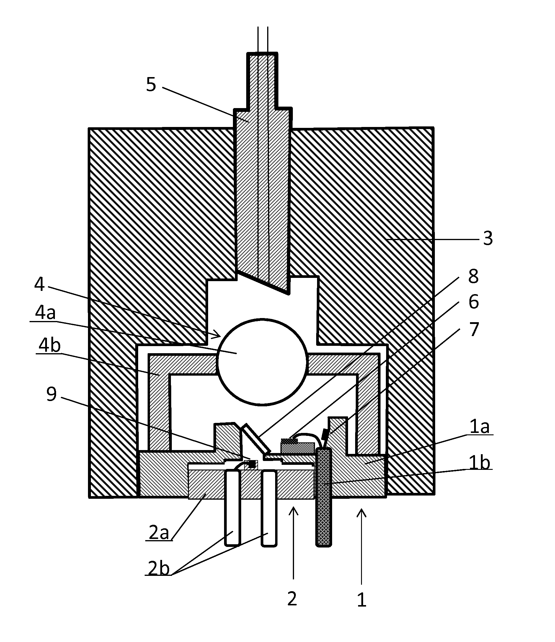
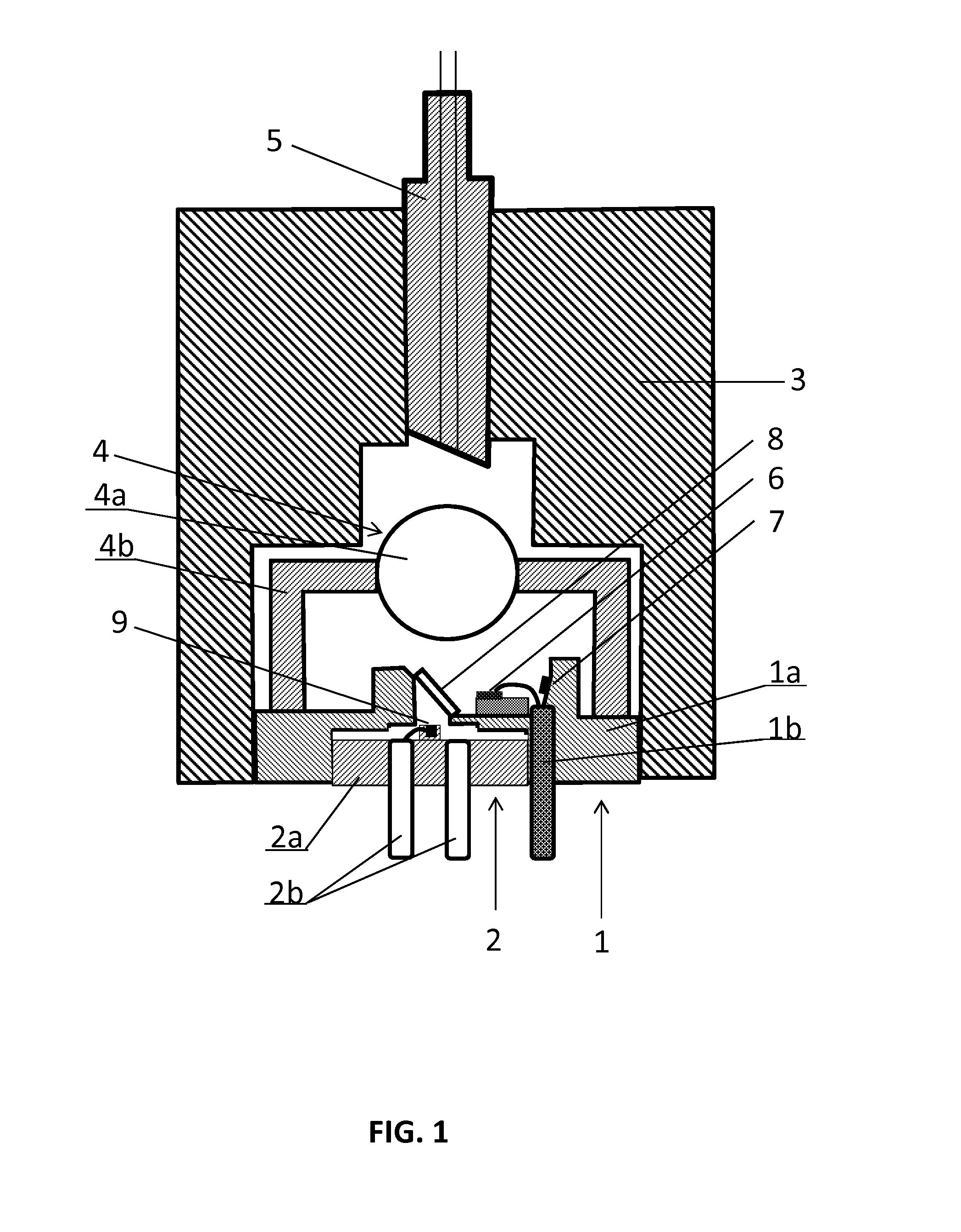
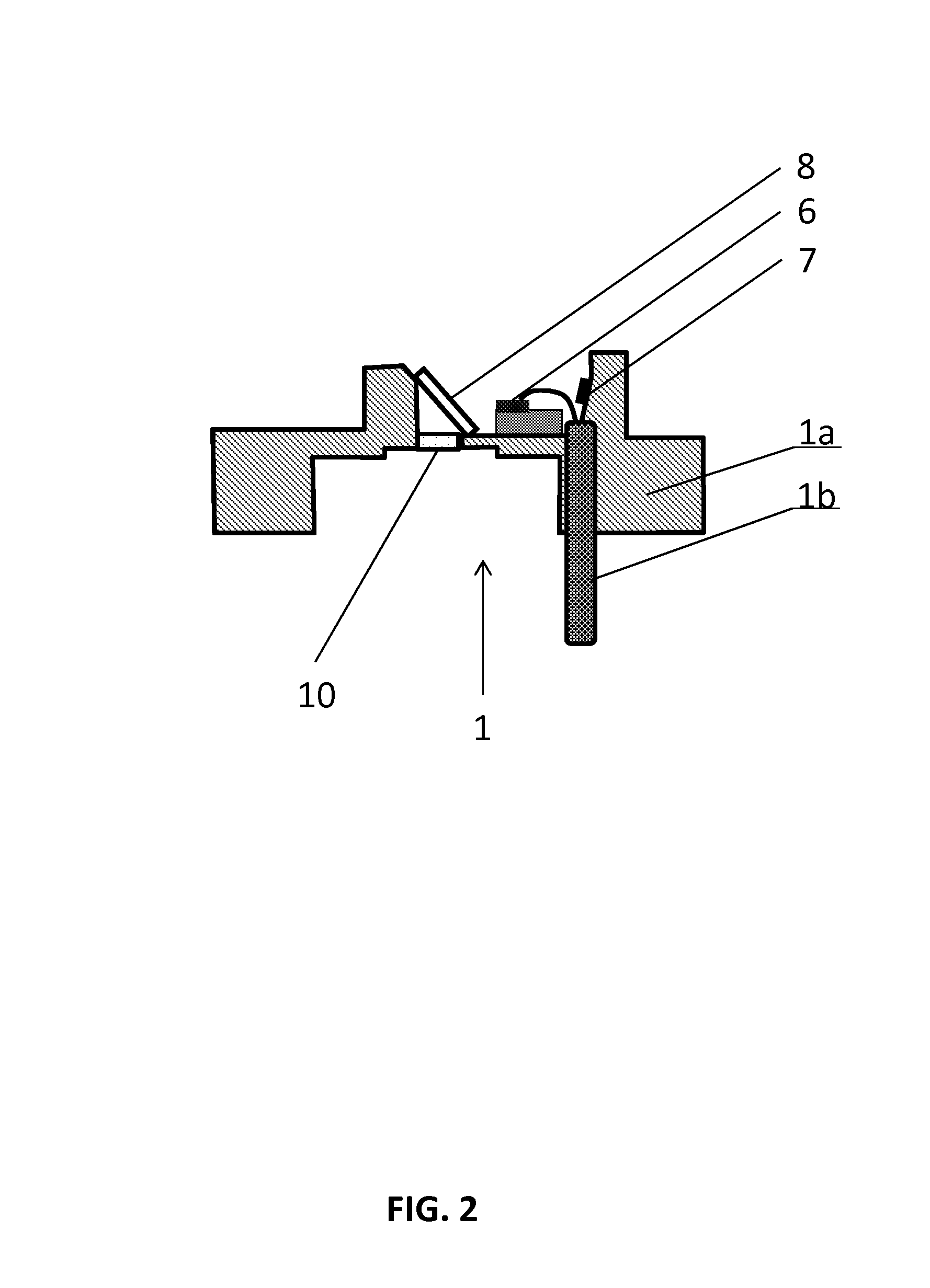
[0016]FIG. 1 schematically illustrates a first embodiment of a two laser optical assembly according to the invention. The two laser optical assembly compromises two laser subassemblies 1 and 2, a mechanical housing 3, a lens assembly 4 and a fiber assembly 5.

[0017]As disclosed in FIG. 1, the laser subassembly 1 comprises the first laser 6 mounted on a base 1a, a monitor photodiode (PD) 7, the leads 1b to provide the electrical connection for the first laser 6 and the monitor PD 7 (only one lead is shown, generally, multiple leads are needed), and a polarization beam combiner (PBC) 8 that is attached to the base 1a. The laser beam from the first laser 6 is parallel to the surface of the base 1a. The polarization direction of the first laser is perpendicular to the incident plane of PBC 8, i.e., it is S-polarized light and is reflected by PBC 8. The first laser assembly 1 can be a transistor outline (TO) can type. The base 1a has a through hole in the center area that allows the secon...


PUM


Abstract

A multiple laser optical assembly comprises two laser subassemblies with two lasers bonded on two bases respectively, a polarization beam combiner (PBC), a lens, a mechanical housing and an optical fiber. The two subassemblies are configured to have orthogonal polarization directions from the two lasers and are assembled coaxially. The PBC combines the orthogonal polarized beams from the two lasers. The lens focuses the combined beam and couples into the optical fiber. With such a two laser optical assembly as a building block and a wavelength division multiplexing (WDM) filter to combine the beams from two of such type of two laser optical assembly, one can further build a four laser optical assembly and extend to even more channel multiple laser optical assembly by adding more WDM filters and more similar two laser optical assemblies.

Description

FIELD OF THE INVENTION[0001]This invention relates to optical assembly in optical communication field. Particularly, this invention relates to a compact optical assembly with multiple semiconductor lasers coupled into a single fiber for high speed optical communication.BACKGROUND OF THE INVENTION[0002]With the wide adoption of smart phone, high definition television and other bandwidth heavy applications, the current optical networks are challenged more than ever to accommodate the exponential traffic growth. Among the obvious options, lighting up more fibers is one of them. Yet this approach will involve installing addition fibers and hardware making this option inadequate and expensive. Another choice is to increase the transmission speed of single carrier. Yet this approach will involve the expensive hardware upgrade and face more technical challenges. The third approach is to stack more wavelengths to existing fibers. This approach will have no need of installing new fibers and ...

Claims


Application Information

Patent Timeline
Patent Type & Authority Applications(United States)
IPC IPC(8): G02B27/28
CPCG02B27/283
Inventor LIU, BIN
Owner LIU BIN
Why Eureka
Try Eureka