Flight vehicle radome and method for producing flight vehicle radome

a technology for flight vehicles and radome, which is applied in the direction of antenna adaptation in movable bodies, other domestic articles, radiating element housings, etc., can solve the problems of difficult to obtain sufficient strength and stiffness in the core of polyimide resins, heavy ceramic materials, impact-vulnerable, etc., and achieves superior mechanical characteristics, excellent transmissivity to radio waves and structural strength, and does not break easily

Inactive Publication Date: 2016-08-11
MITSUBISHI ELECTRIC CORP
View PDF6 Cites 14 Cited by
  • Summary
  • Abstract
  • Description
  • Claims
  • Application Information

AI Technical Summary

Benefits of technology

[0022]The present invention allows configuring a flight vehicle radome in the form of a sandwich structure that results from combining FRP molded bodies, to yield an integrated structure that does not break readily and that boasts thus superior mechanical characteristics, in terms of light weight strength and stiffness, as compared with ceramic radomes, and allows also realizing electric characteristics in...

Problems solved by technology

Conventional technologies have however the following problems.
Heat generation due to transmission loss of radio waves may pose a further problem in cases where wave transmission takes place during flight.
However, ceramic materials are heavy, impact-vulnerable, brittle and fragile, and therefore are not used in manned aircraft, for safety reasons.
Polyimide resins have been problematic however in that sufficient strength and stiffness in a c...

Method used


Image

  • Flight vehicle radome and method for producing flight vehicle radome
  • Flight vehicle radome and method for producing flight vehicle radome
  • Flight vehicle radome and method for producing flight vehicle radome

Examples


embodiment 1

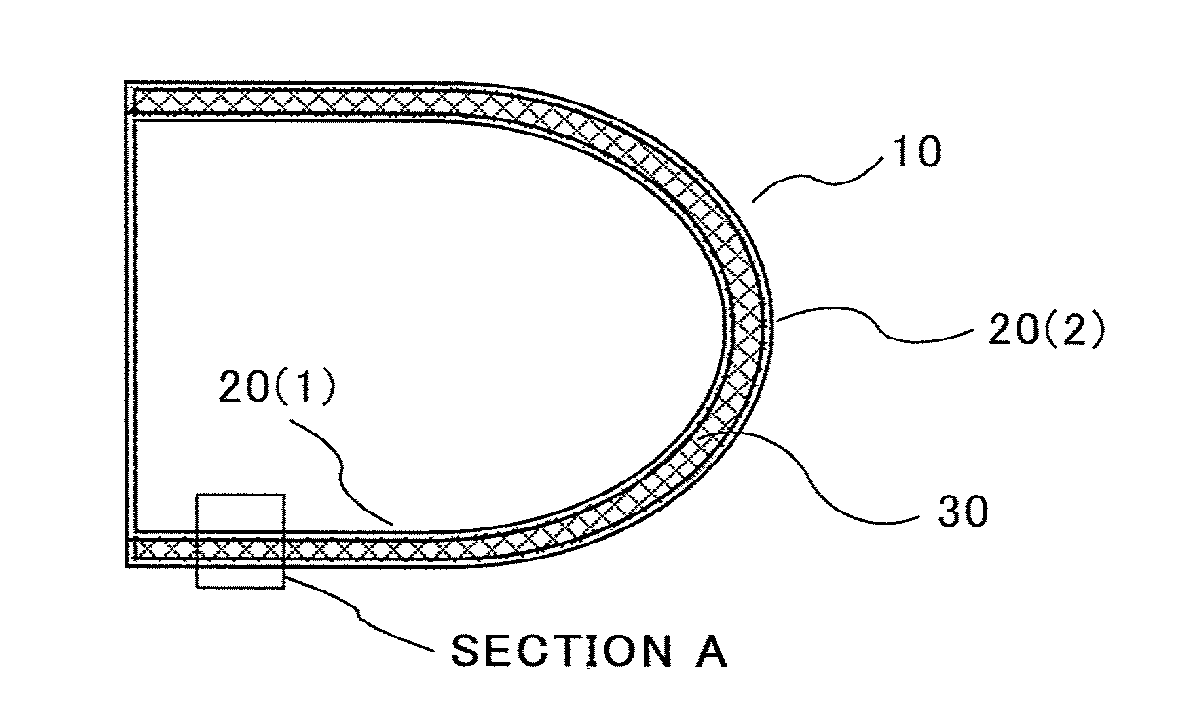
[0030]FIG. 1 is a cross-sectional diagram illustrating a sandwich structure of a radome in Embodiment 1 of the present invention. A radome 10 of the present Embodiment 1 is made up of skin members 20 (1), 20 (2) and a core member 30.

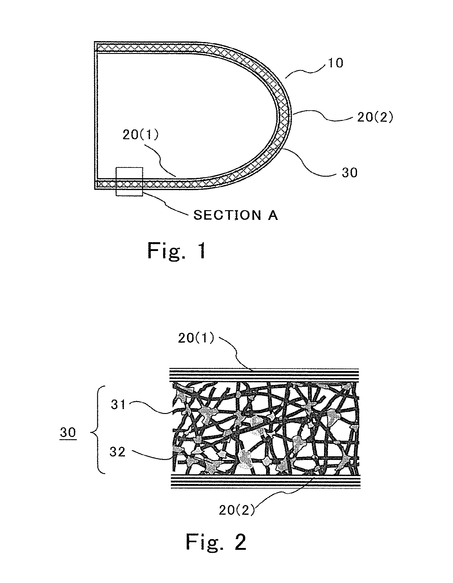
[0031]FIG. 2 is an enlarged-view diagram of a partial cross-section of the sandwich structure of the radome of Embodiment 1 of the present invention. More specifically, the partial cross-sectional diagram illustrated in FIG. 2 corresponds to an enlarged diagram of “section A” in FIG. 1.

[0032]The core member 30 has a structure wherein portions at which reinforcing fibers 31 intersect each other are bonded by a polyimide resin 32. The core member 30 in the present Embodiment 1 is thus is a low-density molded body provided with the reinforcing fibers 31 and the polyimide resin 32. In terms of volume ratio, preferably, the volume content ratio of the reinforcing fibers 31 ranges from 3% to 10% and the volume content ratio of the resin is 20% or lower, the co...

embodiment 2

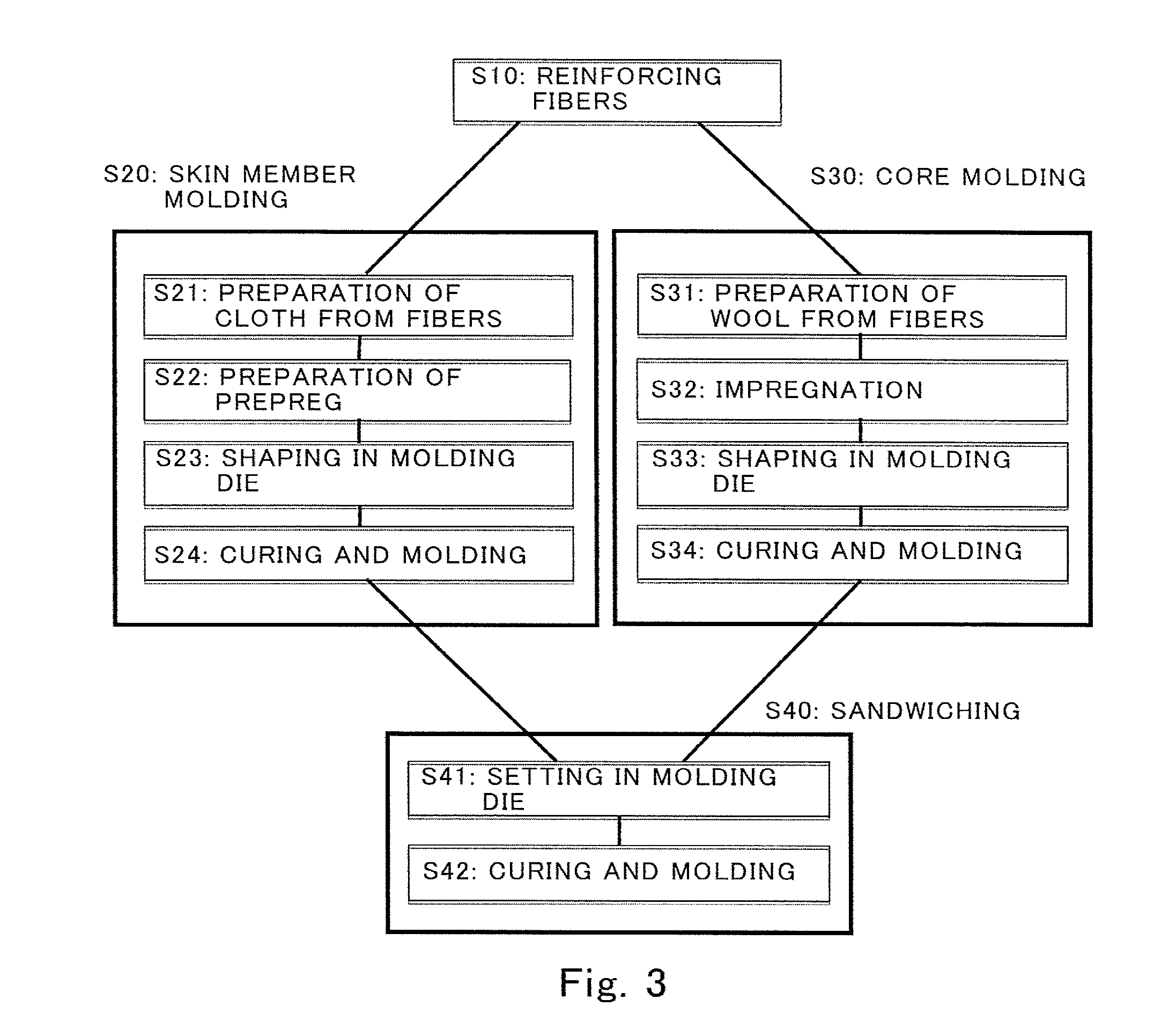
[0054]In Embodiment 2 a production process of the radome of the present invention explained in Embodiment 1 above will be described next with reference to accompanying drawings. FIG. 3 is a flowchart relating to the production process of the radome in Embodiment 2 of the present invention.

[0055]The flowchart illustrated in FIG. 3 includes roughly the following four steps below.

[0056]S10: step of preparing reinforcing fibers that are used in the skin members 20 and the core member 30.

[0057]S20: flow of molding of the skin members 20, made up of four steps S21 to S24.

[0058]S30: flow of molding of the core member 30, made up of four steps S31 to S34.

[0059]S40: flow of sandwiching of the skin members 20 and the core member 30, made up of two steps S41 and S42.

[0060]In step S10, firstly, there are prepared reinforcing fibers (corresponding to the reinforcing fibers 31 and the cloth 21) that are used in the molding flow S20 of the skin members 20 and in the molding flow S30 of the core me...


PUM

PropertyMeasurementUnit
Temperatureaaaaaaaaaa
Lengthaaaaaaaaaa
Fractionaaaaaaaaaa

Abstract

A flight vehicle radome according to the present invention has a shape that covers radio equipment installed in a flight vehicle. The flight vehicle radome is formed of a sandwich panel structure in which a core member (30) resulting from foaming and compositing of a heat-resistant resin (32) and insulating reinforcing fibers (31) is sandwiched between skin members (20) made of a fiber reinforced material being a composite of quartz cloth (20) and a heat-resistant resin (22).

Description

BACKGROUND OF THE INVENTION[0001]1. Field of the Invention[0002]The present invention relates to a flight vehicle radome that protects radio equipment installed in a flight vehicle such as aircraft, from the external environment, and to a method for producing a flight vehicle radome.[0003]2. Description of the Related Art[0004]Radio equipment such as various kinds of antennas and radar are installed in flight vehicles such as aircraft. Such radio equipment is protected from the external environment by being covered by a radome. Radomes are required to be not only durable, in terms of being capable of protecting the radio equipment, but also to exhibit radio characteristics in terms of enabling sufficient transmission of the radio waves that are exchanged by the radio equipment.[0005]The specific configuration of radomes for flight vehicles is not particularly limited. However, further reductions in the weight of aircraft have come to be demanded in recent years, for instance from th...

Claims


Application Information

Patent Timeline
IPC IPC(8): H01Q1/42B29C65/48B29C70/34H01Q1/28B29C70/16
CPCH01Q1/422H01Q1/28B29C70/16B29C70/34B29C65/48B29K2309/14B29L2031/3076B29K2079/08B29K2105/04B29K2995/0016B29L2009/00B29L2031/3456B29K2105/0845B29C65/02B29C66/1122B29C66/545B29C66/63B29C66/71B29C66/7212B29C66/72141B29C66/73753B29C66/73755B29C66/8322B29C70/026B29C70/086
Inventor KUME, MASAMIKOBAYASHI, HIROKI
Owner MITSUBISHI ELECTRIC CORP
Why Eureka
Try Eureka