Power-supply device
- Summary
- Abstract
- Description
- Claims
- Application Information
AI Technical Summary
Benefits of technology
Problems solved by technology
Method used
Image
Examples
embodiment 1
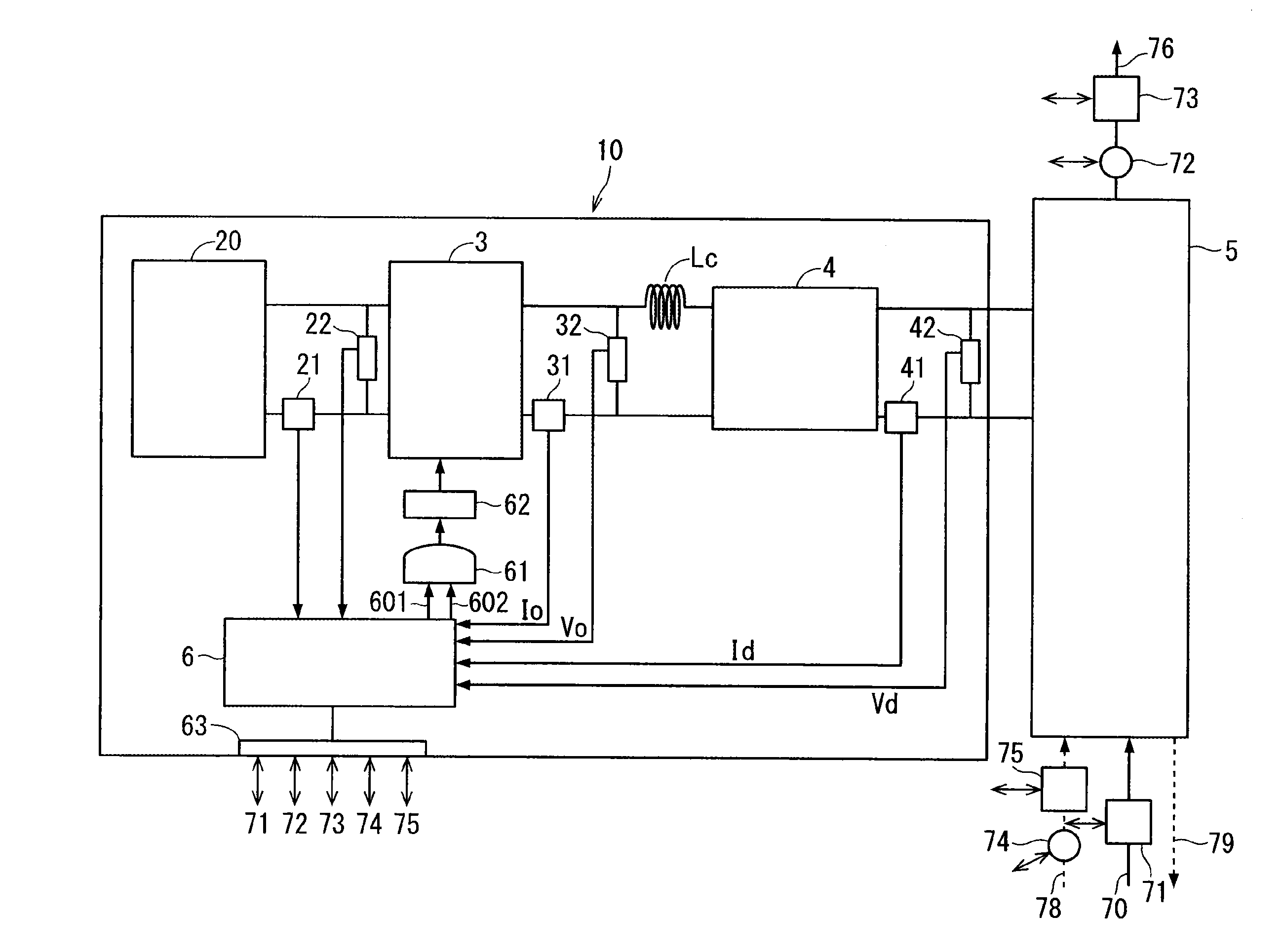
[0048]With a view toward protecting the load against a short circuit, the power supply apparatus 10 according to the present embodiment includes, in place of fuses for the respective discharge cells, a protection coordination function that protects the load against a short circuit occurring downstream from the inverter output unit. The power supply apparatus 10 is configured to interrupt the inverter output voltage in a very short period of time when any abnormality is encountered. Thus, the power supply apparatus 10 according to the present embodiment is ready to manage failures. Further, the power supply apparatus 10 according to the present embodiment indicates a faulty part in the event of a failure. This indication helps the user to restore the malfunctioning power supply apparatus 10 in a short period of time.
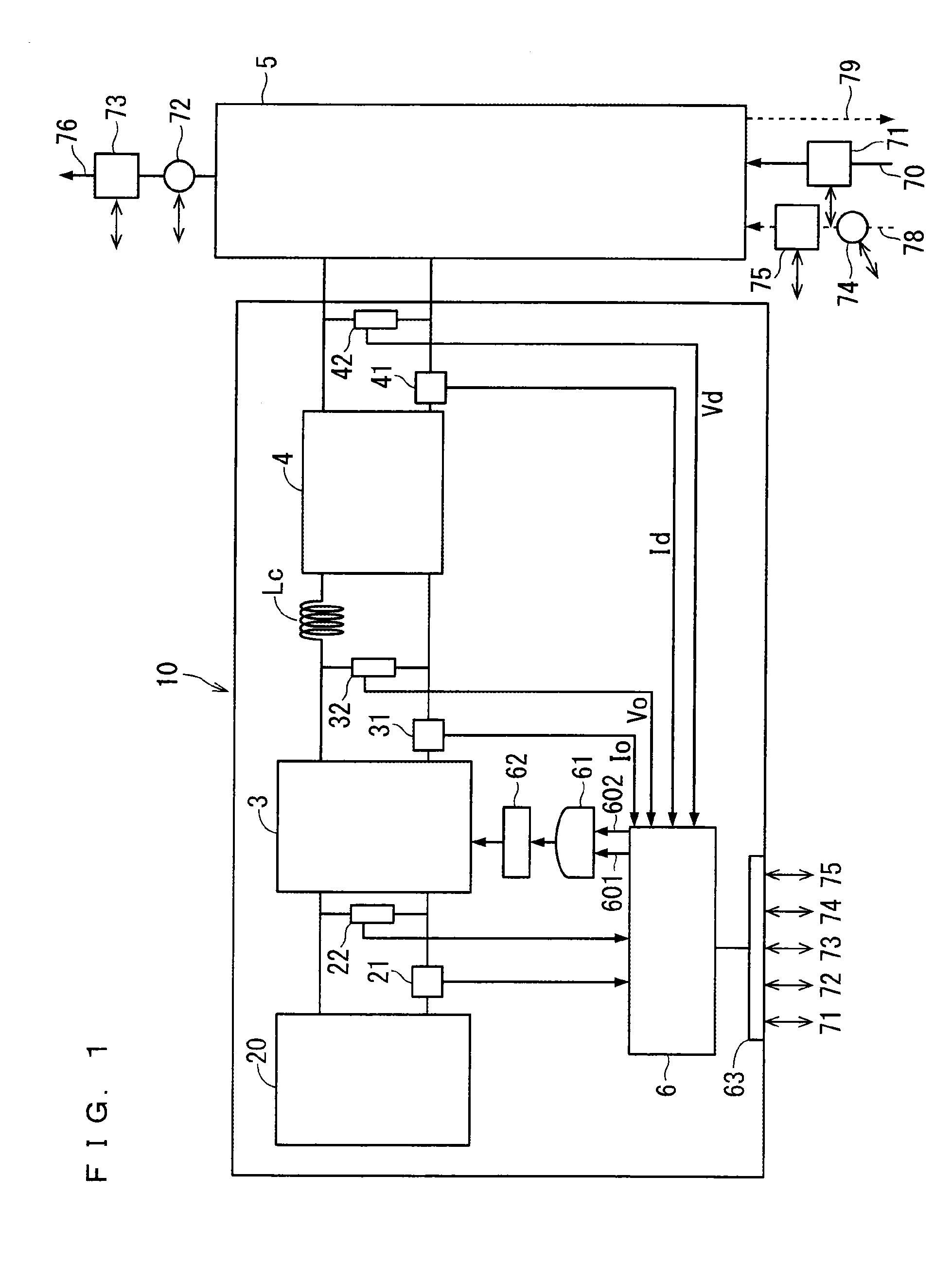
[0049]As shown in FIG. 1, the power supply apparatus 10 includes a direct-current voltage output unit 20, an inverter 3, and a transformer 4.
[0050]The direct-current volt...
embodiment 2
[0088]As described below, the power supply apparatus 10 according to the present embodiment has a configuration that is based on the parallel resonance and highly resistant to load variations.
[0089]For the capacitive load such as the plasma generator 5, the phase of the current is approximately 90° leading relative to the phase of the voltage waveform. Although the electric capacitance supplied to the plasma generator 5 is extremely great, the stable inputting of energy to the plasma generator 5 can be achieved only if the active power is in the range of about ⅕ to 1 / 10 of the electric capacitance (the load power factor is in the range of about 10% to 20%). Therefore, the power supply apparatus 10 has been in need of an extremely large electric capacity. Here, the inductive reactor is disposed for the power factor improvement associated with the load power factor of the power supply apparatus 10 (to create the resonance state between the plasma generator 5 and the power supply appar...
embodiment 3
[0147]In the embodiment 1, the description has been given on the case in which the current-limiting reactor Lc is disposed between the output unit of the inverter 3 and the input unit of the transformer 4 (see FIG. 1). In the present embodiment, the inductance of the primary-side coil of the high-performance transformer 4 is also equipped with the function of the current-limiting reactor Lc. Thus, the physical components of the current-limiting reactor Lc can be omitted, and accordingly power supply apparatus 10 can be configured to include the main circuit that is formed exclusively of the direct-current voltage output unit 20, the inverter portion, and the high-performance transformer 4. The transformer 4 according to the present embodiment will be described below.
[0148]The primary-side leakage inductance and / or the primary-side magnetizing inductance of the transformer 4 takes over the inductance component of the current-limiting reactor Lc such that the transformer 4 is equipped...
PUM
 Abstract
Description
Claims
Application Information
 - R&D
- Intellectual Property
- Life Sciences
- Materials
- Tech Scout
- Unparalleled Data Quality
- Higher Quality Content
- 60% Fewer Hallucinations
Browse by: Latest US Patents, China's latest patents, Technical Efficacy Thesaurus, Application Domain, Technology Topic, Popular Technical Reports.
© 2025 PatSnap. All rights reserved.Legal|Privacy policy|Modern Slavery Act Transparency Statement|Sitemap|About US| Contact US: help@patsnap.com


