Connector for aseptic connection

Active Publication Date: 2016-08-18
CYTIVA SWEDEN AB
View PDF1 Cites 4 Cited by
  • Summary
  • Abstract
  • Description
  • Claims
  • Application Information

AI Technical Summary

Benefits of technology

[0012]The terms aseptic and sterile are herein used interchangeably and mean that the concentration of viable microorganisms is reduced

Problems solved by technology

However, maintaining a clean room is time consuming, difficult and costly to validate.
A tube welding machine is however also usually limited in applicability to specific tube size and materials, such as thermoplastic tubing.
Furthermore, tube welding machines are typically large, heavy, lack ve

Method used


Image

  • Connector for aseptic connection
  • Connector for aseptic connection
  • Connector for aseptic connection

Examples


Example

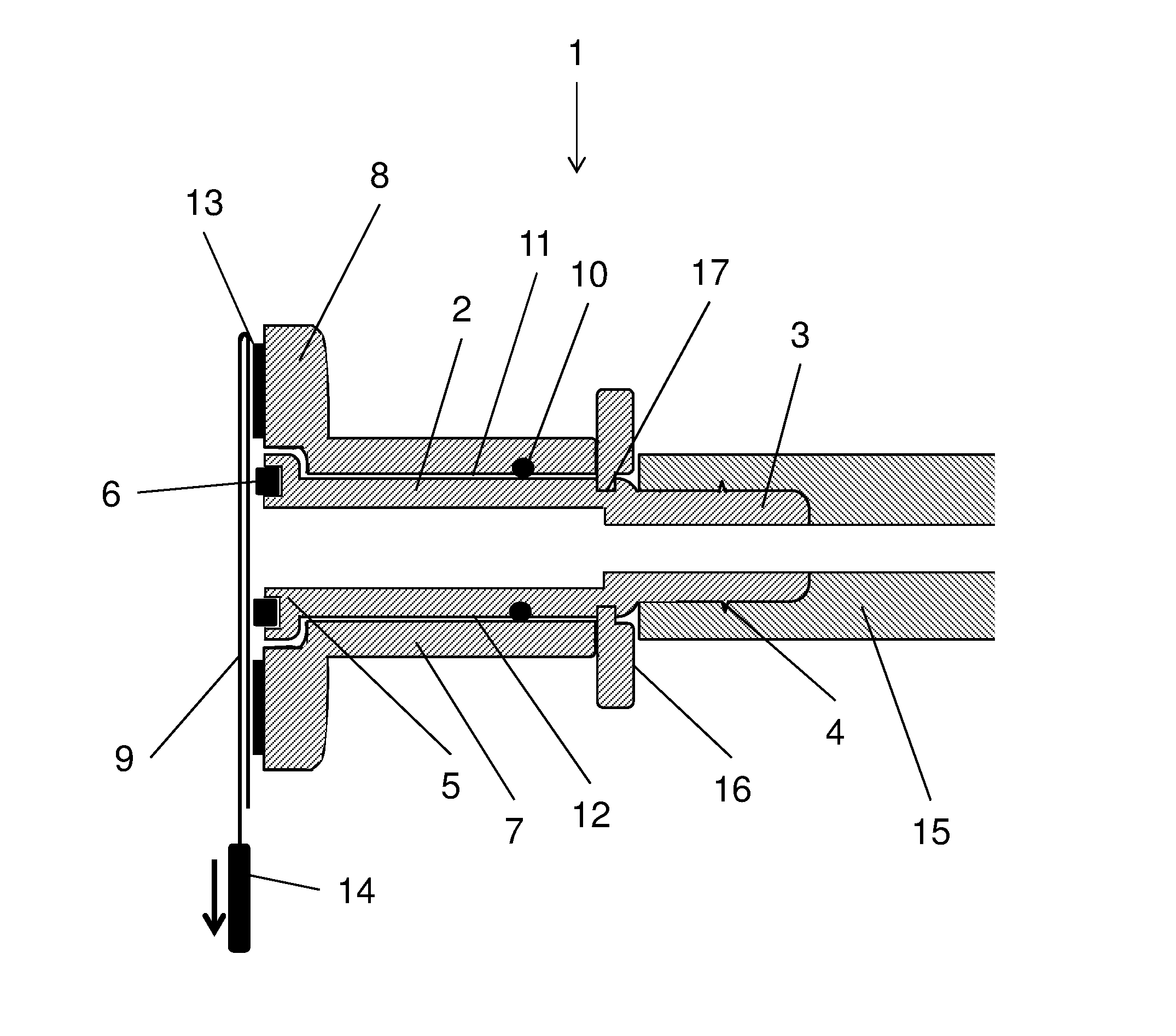
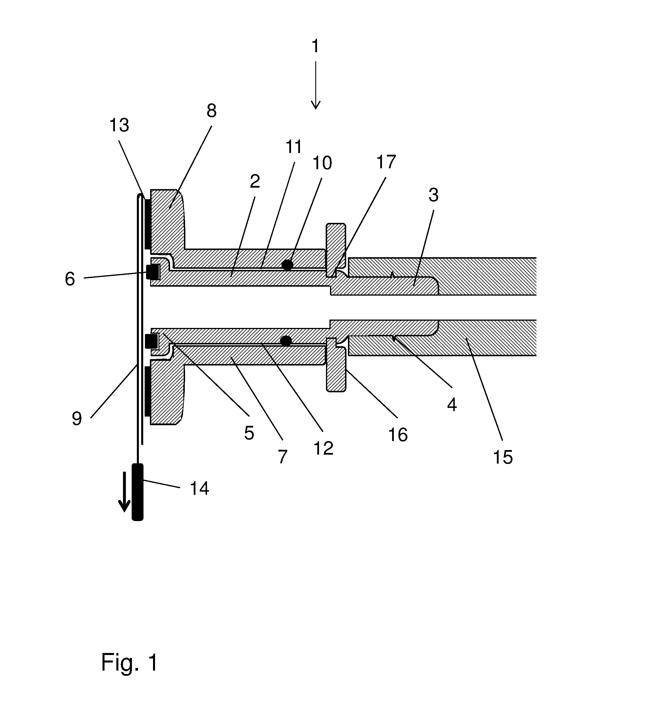
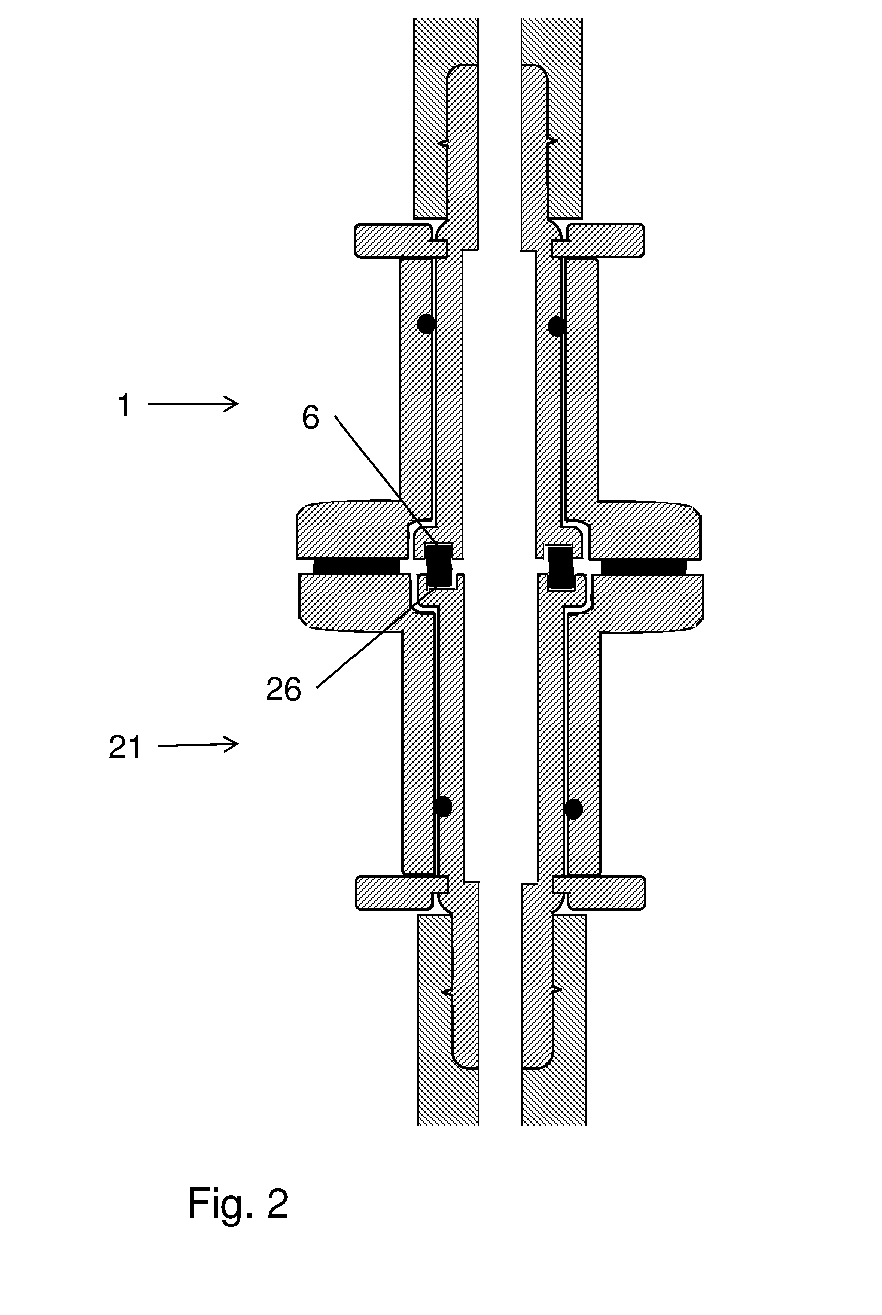
[0015]In one aspect the present invention discloses a connector 1 for substantially aseptic or for aseptic connection of tubing. The connector comprises:

[0016]a) a central tubular and elongated stem member 2, which has a line connection end 3 (to which a length of tubing 15 can be firmly attached) and a coupling end 5 where an annular gasket 6, e.g. an O-ring or a gasket with rectangular cross-section, is fitted on the coupling end. The annular gasket is arranged to engage a similar annular gasket 26 on a similar second connector 21 in sealing abutment. Suitably, the annular gasket can extend in a plane transverse to the longitudinal axis of the stem member and it may e.g. be mounted in an annular recess at the extremity of the coupling end. From the functional point of view, the stem member provides fluid transport through the tubular center, connection to tubing etc. at the line connection end and sealing towards an opposite connector at the coupling end. and;

[0017]b) a tubular so...


PUM


Abstract

The invention discloses a connector (1) for substantially aseptic connection of tubing, comprising:
    • a) a central tubular stem member (2) with a line connection end (3) and a coupling end (5) having an annular gasket (6) arranged to engage a similar annular gasket (26) on a similar second connector (21) in sealing abutment and;
    • b) a tubular socket member (7), concentrically arranged outside the stem member, having a flange (8) concentrically arranged outside the coupling end and comprising a cover film (9) releasably bonded to the flange and covering the coupling end of the stem member, the annular gasket and at least a portion of the flange;
    • wherein the socket member is rotatable around the stem member and wherein the connector further comprises an annular seal member (10) in sealing abutment between an inside (11) of the socket member and an outside (12) of the stem member.

Description

TECHNICAL FIELD OF THE INVENTION[0001]The present invention relates to connectors, and more particularly to aseptic connectors for use e.g. bioprocessing. The invention also relates to systems connected with aseptic connectors.BACKGROUND OF THE INVENTION[0002]The biotechnology industry uses different manufacturing systems for creating aseptic and sterile connections between process containers and equipment, such as plastic bags and pumps. A known manufacturing system uses controlled environments such as clean rooms or cabinets to ensure aseptic connections during manufacture. When necessary connections are made in such a controlled environment that breaches sterile tubing and piping, the environment does not contaminate the fluid flow passage. However, maintaining a clean room is time consuming, difficult and costly to validate.[0003]Another known manufacturing system uses disposable plastic bags connected to flexible thermoplastic tubing, which requires special connections to assur...

Claims


Application Information

Patent Timeline
IPC IPC(8): A61M39/10A61M39/16
CPCA61M39/18A61M39/16A61M2039/1027A61M39/165A61M39/10A61M39/1055C12M37/04F16L2201/44
Inventor GEBAUER, KLAUS
Owner CYTIVA SWEDEN AB
Why Eureka
Try Eureka