
Near infrared optical interference filters with improved transmission

a technology of optical interference filter and transmission, applied in the field of optical arts and optical filter arts, can solve the problem of limiting the useful bandwidth of the filter by the amount of angle shi

Inactive Publication Date: 2016-08-18
MATERION
View PDF5 Cites 46 Cited by
  • Summary
  • Abstract
  • Description
  • Claims
  • Application Information

AI Technical Summary

Benefits of technology

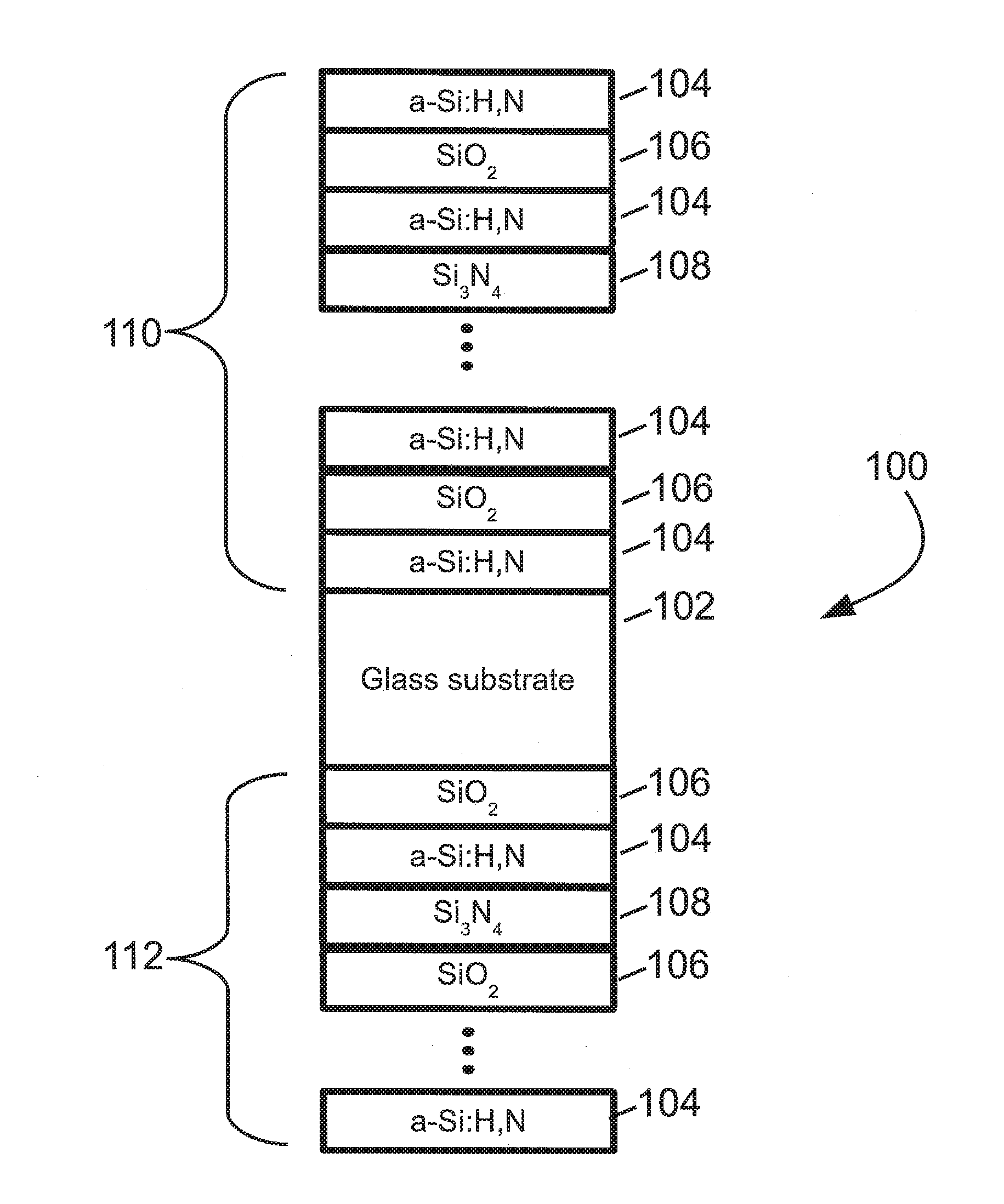
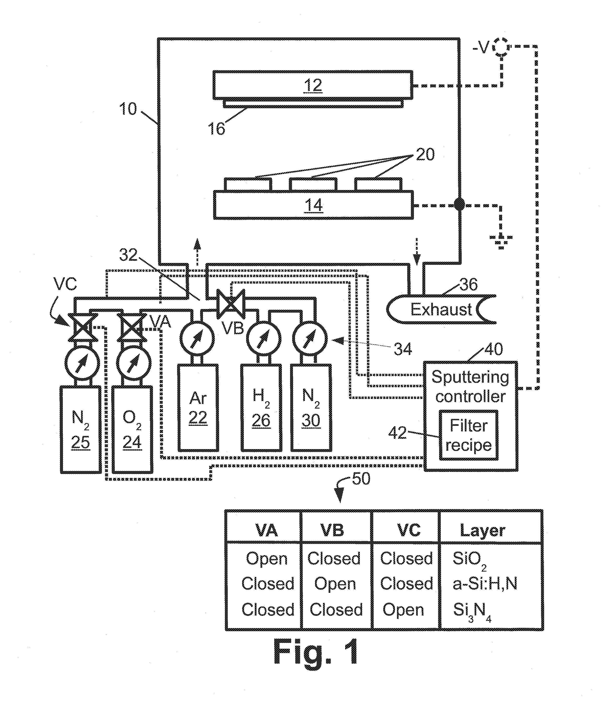
This patent describes an interference filter made from layers of amorphous hydrogenated silicon, a-Si:H,N, and dielectric materials having a lower refractive index. The filter has a specific passband in the range of 750-1,110 nm. The layers are deposited using a process gas that alternates between hydrogen and nitrogen for the a-Si:H,N layers, and oxygen for the dielectric layers. The interference filter can improve the performance of optical devices by reducing interference and improving optical transmission.

Problems solved by technology

For narrow band filters the amount of angle shift limits the useful bandwidth of the filter when used in optical systems.

Method used


Image

  • Near infrared optical interference filters with improved transmission
  • Near infrared optical interference filters with improved transmission
  • Near infrared optical interference filters with improved transmission

Examples


Embodiment Construction

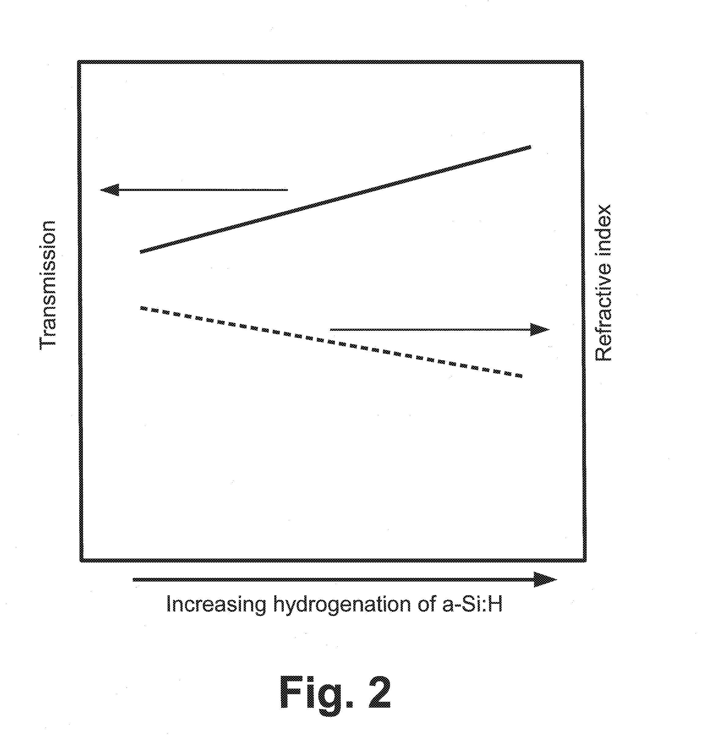
[0014]As previously noted, an interference filter comprising a stack of layer units with hydrogenated silicon (a-Si:H) layers is used for operation in the near infrared (800-1250 nm), because the hydrogenation of the silicon decreases the absorption losses (both from intrinsic silicon and disorder induced) sufficiently to provide acceptable filter transmission characteristics in the passband. With brief reference to FIG. 2, it is recognized herein that this approach for the near-infrared has a substantial disadvantage. As seen in diagrammatic FIG. 2, for a fixed wavelength in the infrared (e.g. in the range 800-1100 nm), increasing hydrogenation of the a-Si:H (that is to say, increasing the hydrogen content of the a-Si:H) does decrease the loss—however it also decreases the refractive index of the a-Si:H as diagrammatically depicted in FIG. 2.

[0015]The performance of narrow band interference filters for high numerical aperture optical systems is a compromise between obtaining high t...


PUM

PropertyMeasurementUnit
Fractionaaaaaaaaaa
Fractionaaaaaaaaaa
Fractionaaaaaaaaaa

Abstract

An interference filter includes a layers stack comprising a plurality of layers of at least: layers of amorphous hydrogenated silicon with added nitrogen (a-Si:H,N) and layers of one or more dielectric materials, such as SiO2, SiOx, SiOxNy, a dielectric material with a higher refractive index in the range 1.9 to 2.7 inclusive, or so forth. The interference filter is designed to have a passband center wavelength in the range 750-1000 nm inclusive. Added nitrogen in the a-Si:H,N layers provides improved transmission in the passband without a large decrease in refractive index observed in a-Si:H with comparable transmission. Layers of a dielectric material with a higher refractive index in the range 1.9 to 2.7 inclusive provide a smaller angle shift compared with a similar interference filter using SiO2 as the low index layers.

Description

[0001]This application claims the benefit of U.S. Provisional Application No. 62 / 117,598 filed Feb. 18, 2015 and titled “NEAR INFRARED OPTICAL INTERFERENCE FILTERS WITH IMPROVED TRANSMISSION”. U.S. Provisional Application No. 62 / 117,598 filed Feb. 18, 2015 is incorporated herein by reference in its entirety.BACKGROUND[0002]The following relates to the optical arts, optical filter arts, and related arts.[0003]A known transmission interference filter employs a stack of alternating silicon and silicon dioxide (SiO2) layers. Such devices are known for use in the short wave and mid wave infrared down to about 1100 nm, as both silicon and SiO2 are transparent in this range. The lower wavelength threshold (corresponding to the upper photon energy threshold) is controlled by the onset of absorption by the silicon, which in its crystalline form has a bandgap of about 1.12 eV. A key advantage of silicon in these devices is its high refractive index. The spectral profile of an optical interfer...

Claims


Application Information

Patent Timeline
IPC IPC(8): G02B5/28C23C14/34C23C14/06C23C14/14C23C14/10
CPCG02B5/281C23C14/14C23C14/10C23C14/3457C23C14/06C23C14/3414C23C14/0652C23C14/0036C23C14/0057G02B5/285G02B1/10
Inventor SPRAGUE, ROBERTBAI, SHENGYUAN
Owner MATERION
Learn More