Thermal spray powder

a technology of spray powder and spray powder, which is applied in the direction of molten spray coating, coating, electric discharge tube, etc., can solve the problems of advanced erosion caused by erosive plasma, and achieve the effects of good corrosion resistance, good corrosion resistance and good corrosion resistan

Active Publication Date: 2016-08-25
FUJIMI INCORPORATED
View PDF2 Cites 17 Cited by
  • Summary
  • Abstract
  • Description
  • Claims
  • Application Information

AI Technical Summary

Benefits of technology

[0015]In a preferred mode of the thermal spray powder disclosed herein, the average particle size of the ceramic particles (including the secondary particles) is 1 μm or more and 20 μm or less. Since the thermal spray powder disclosed herein is compact, a thermal spray coating that has few pores and excellent erosion resistance can be formed in a comparatively broad particle size range such as indicated hereinabove.
[0016]In a preferred mode of the thermal spray powder disclosed herein, the ceramic material includes a halogen atom. With such a feature, the melting point of the ceramic material can be lowered. Further, when a thermal spray coating is formed using the thermal spray powder, the thermal spray powder is entirely melted, the presence of remaining unmelted particles can be suppressed more reliably, and through pores can be reduced.
[0017]In another aspect, the technique disclosed herein provides a thermal spray coating. The thermal spray coating is obtained by thermally spraying the thermal spray powder described hereinabove. As a result, a compact thermal spray coating that excels in durability and has good adhesion to a base material can be obtained.

Problems solved by technology

However, even with the thermal spray coating formed by using such conventional thermal spray particles, when the coating is used over a long period of time, the erosion induced by erosive plasma is advanced.

Method used


Image

  • Thermal spray powder
  • Thermal spray powder
  • Thermal spray powder

Examples


Embodiment Construction

[0020]The thermal spray powder in accordance with the present invention will be described hereinbelow on the basis of the preferred embodiment with reference to the appended drawings. Matters which are necessary for implementing the present invention (for example, a method for thermally spraying the thermal spray powder) and which are not particularly referred to in the present specification can be understood as design matters for a person skilled in the art that are based on the related art in the pertinent field. The present invention can be implemented on the basis of the contents disclosed in the present specification and common technical knowledge in the pertinent field.

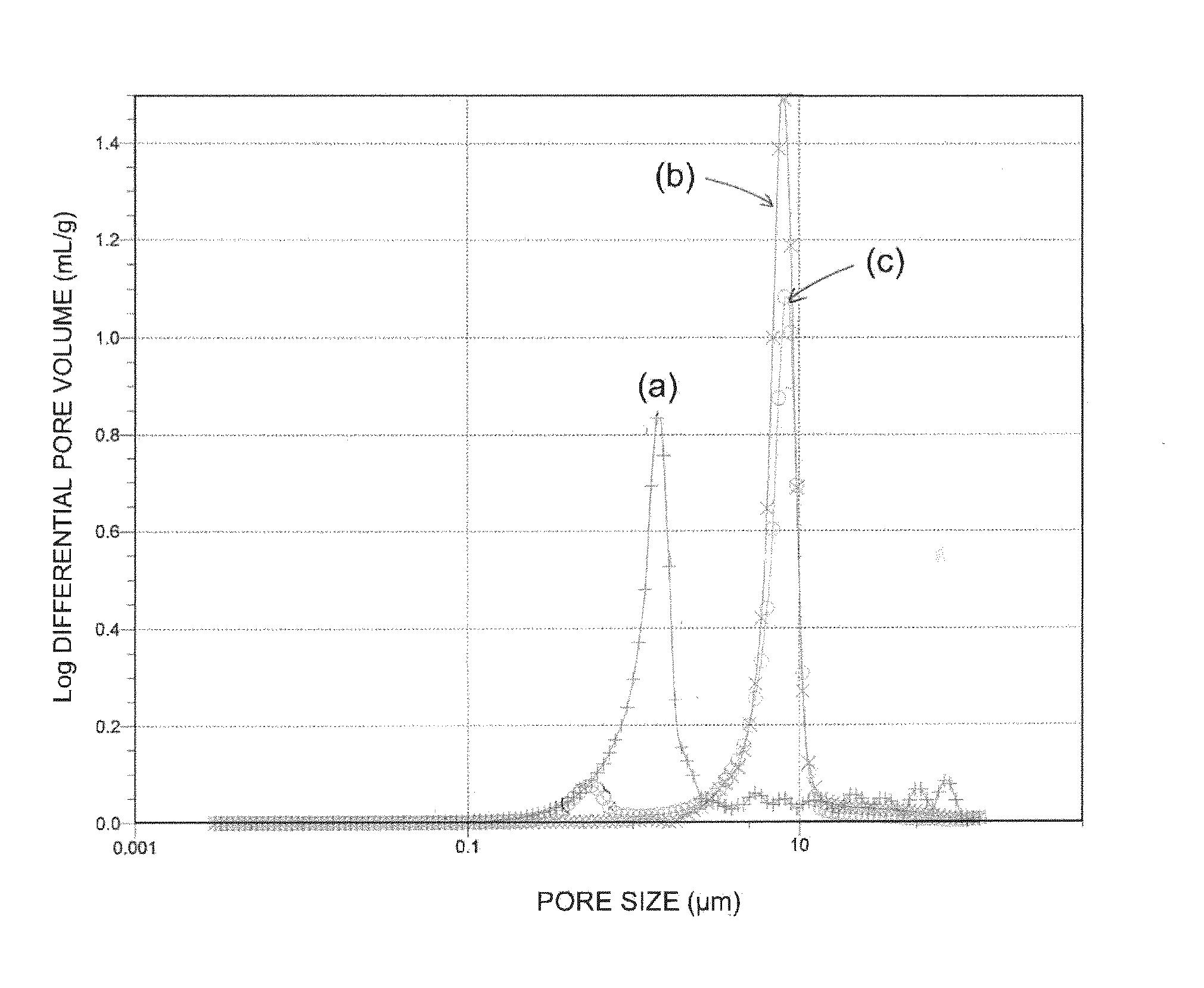
[0021]FIG. 1 shows a log differential pore volume distribution curve relating to: (a) a thermal spray powder according to an embodiment; (b) a thermal spray powder which is called a melt pulverized powder, and (c) a thermal spray powder which is called a granulated and sintered powder.

[0022]The thermal spray pow...


PUM

PropertyMeasurementUnit
melting pointaaaaaaaaaa
particle sizeaaaaaaaaaa

Abstract

Provided is a compact thermal spray powder suitable for forming a ceramic thermal spray coating which is compact and excels in durability. The thermal spray powder disclosed herein includes ceramic particles formed of a ceramic material with a melting point equal to or lower than 2000° C. The thermal spray powder is configured such that the peak top of a main peak is in a range of 10 μm or less in a log differential pore volume distribution obtained by a mercury porosimetry, and when the peak top of a second peak is at a fine pore size less than that of the peak top of the main peak, the ratio (H2/H1) of the height H2 of the second peak to the height H1 of the main peak is 0.05 or less.

Description

CROSS-REFERENCE[0001]The present application claims priority to Japanese Patent Application No. 2015-034086, filed on Feb. 24, 2015, the entire contents of which are hereby incorporated by reference.BACKGROUND OF THE INVENTION[0002]1. Field of the Invention[0003]The present invention relates to a thermal spray powder including ceramic particles.[0004]2. Description of the Related Art[0005]In the field of fabrication of semiconductor devices or the like, the surface of a semiconductor substrate is generally subjected to fine processing by dry etching using plasma of a halogen gas such as fluorine, chlorine, and bromine. After the dry etching, the interior of the chamber from which the semiconductor substrate has been removed is cleaned using oxygen gas plasma. At this time, parts inside the chamber which are exposed to highly reactive oxygen gas plasma or halogen gas plasma can be eroded. Where the eroded portions fall off in the form of particles from the parts, the particles can be...

Claims


Application Information

Patent Timeline
Patent Type & Authority Applications(United States)
IPC IPC(8): C23C4/04H01J37/32C04B35/622
CPCC23C4/04H01J2237/32H01J37/32495C04B35/62222H01J37/3288H01J37/32477C04B35/111C04B35/505C04B35/5152C04B35/553C04B2235/5436C04B2235/77C04B2235/96
Inventor IBE, HIROYUKITSUZUKI, KAZUYUKI
Owner FUJIMI INCORPORATED
Why Eureka
Try Eureka