Dyeing device and dyeing apparatus
a dyeing device and dyeing technology, applied in the direction of dyeing process, textile treatment carrier, liquid/gas/vapor treatment of indefinite length materials, etc., can solve the problems of high pressure pipeline cleaning procedures, low overall process efficiency, and high pressure space. , the effect of favorable dyeing
- Summary
- Abstract
- Description
- Claims
- Application Information
AI Technical Summary
Benefits of technology
Problems solved by technology
Method used
Image

Examples
first embodiment
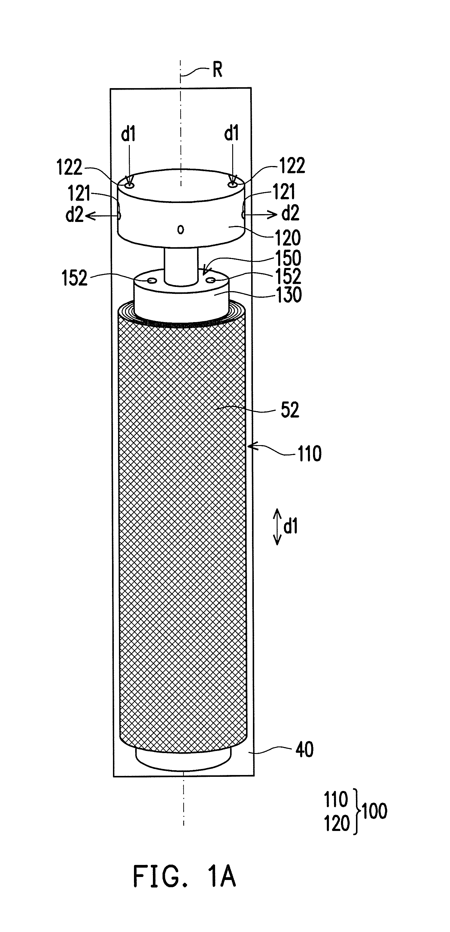
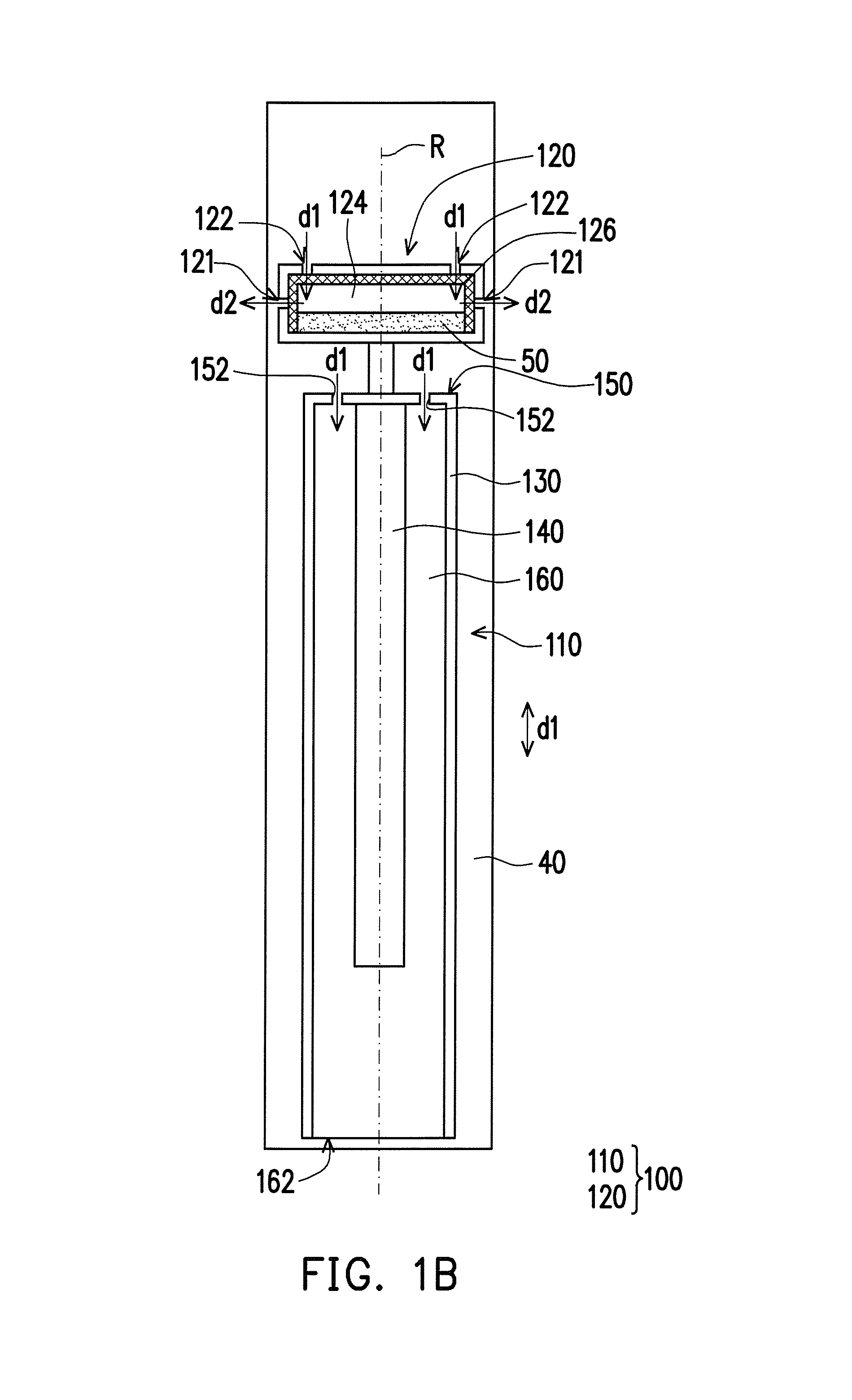
[0038]On the other hand, in the present embodiment, directions for the fluid to flow in and out of the dye mixing chamber 120 are not limited to the aforementioned first and second directions d1 and d2; that is to say, the aforementioned directions d1 and d2 are merely provided for explaining an exemplary flowing path for the fluid in the dye mixing chamber 120, but the invention is not limited thereto. In detail, referring to FIG. 1B, in the invention, the dye mixing chamber 120 includes a chamber 124 and a plurality of through holes 121 and 122. The dye 50 is disposed in the chamber 124, the through holes 121 and 122 connect the chamber 124 with the high pressure space 40, and the through holes 121 and 122 allow the fluid in the high pressure space 40 to flow in and out of the chamber 124, but the invention does not limit a flowing direction of the fluid in each of the through holes 121 and 122. The through holes 122 of the present embodiment are located at a surface of the dye mi...
second embodiment
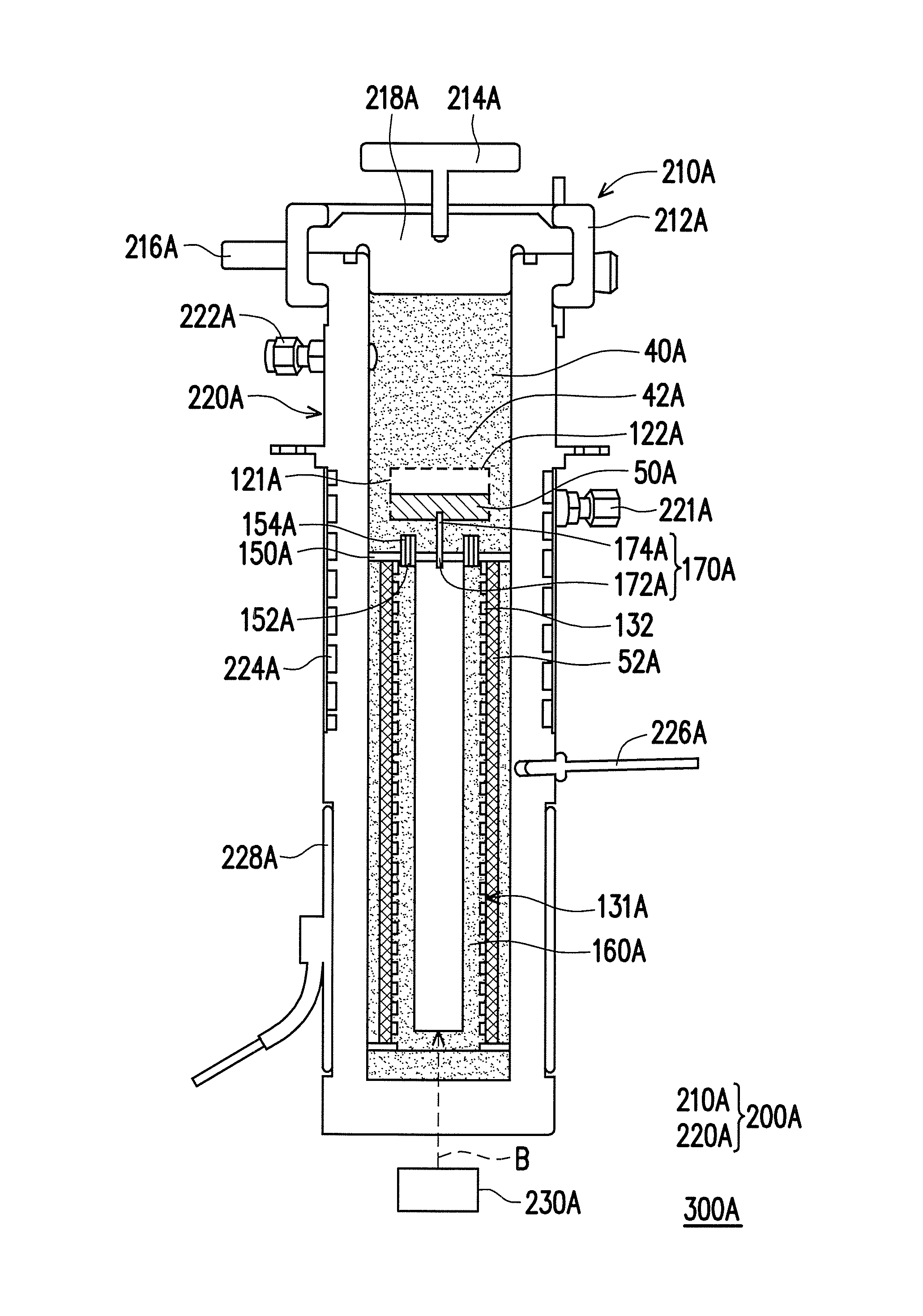
[0044]FIG. 2A is a schematic diagram illustrating a dyeing device according to the invention. FIG. 2B is a cross-sectional diagram illustrating a dyeing apparatus including the dyeing device of FIG. 2A. It is to be noted that the following embodiment has adopted element notations and part of the contents from the previous embodiment, wherein the same notations are used for representing the same or similar elements, and descriptions of the same technical contents are omitted. The descriptions regarding the omitted part may be referred to the previous embodiment, and thus are not repeated herein. Referring to FIG. 2A and FIG. 2B, a dyeing apparatus 300A includes a dyeing device 100A, a high pressure steel module 200A accommodating the dyeing device 100A and a fluid 42A, and a magnetic unit 230A. The high pressure steel module 200A includes a cover body 210A and a high pressure accommodating chamber 220A, and the high pressure accommodating chamber 220A and the cover body 210A are conf...
PUM
| Property | Measurement | Unit |
|---|---|---|
| Time | aaaaa | aaaaa |
| Pressure | aaaaa | aaaaa |
Abstract
Description
Claims
Application Information
 - R&D
- Intellectual Property
- Life Sciences
- Materials
- Tech Scout
- Unparalleled Data Quality
- Higher Quality Content
- 60% Fewer Hallucinations
Browse by: Latest US Patents, China's latest patents, Technical Efficacy Thesaurus, Application Domain, Technology Topic, Popular Technical Reports.
© 2025 PatSnap. All rights reserved.Legal|Privacy policy|Modern Slavery Act Transparency Statement|Sitemap|About US| Contact US: help@patsnap.com