Ionization apparatus

a technology of ionization apparatus and ionization cylinder, which is applied in the direction of particle separator tube details, electric discharge tube, particle separator tube, etc., can solve the problems of difficult to achieve high analysis sensitivity, and disadvantages of extracting mode and repelling mode in terms of achieving stability of sensitivity, so as to reduce the amount of ions to be used for mass spectrometry, the effect of suppressing ion loss and increasing the amount of ion loss

Inactive Publication Date: 2016-08-25
SHIMADZU CORP
View PDF5 Cites 15 Cited by
  • Summary
  • Abstract
  • Description
  • Claims
  • Application Information

AI Technical Summary

Benefits of technology

[0028]In the ionization apparatus according to the present invention, with the use of both the ion repelling action of the repeller electrode arranged inside of the ionization chamber and the ion focusing action of the ion focusing electrode arranged outside of the ionization chamber, the ions produced in the ionization chamber are led to the ion emission port, and are sent out to the subsequent stage through the ion emission port. Consequently, an ion loss can be suppressed compared with an ionization apparatus using the conventional repelling mode, and a larger amount of ions can be sent out from the ion emission port. In addition, even if the charge-up phenomenon occurs along with long-term use of the apparatus, a change in ion trajectories can be reduced. As a result, with the ionization apparatus according to the present invention used as an ion source of a mass spectrometer, the amount of ions to be used for mass spectrometry increases, enhancement of the analysis sensitivity can be achieved, and such high sensitivity can be maintained over a long period.

Problems solved by technology

However, as described below, it is difficult to achieve both high sensitivity and the stability of the sensitivity in the conventional ionization apparatuses.
As a result, in the repelling mode, only the ions produced in a relatively narrow region around the center of the ionization chamber 31 can be mainly used for mass spectrometry, and it is difficult to achieve high analysis sensitivity.
However, according to studies made by the inventor of the present application, the extracting mode is more disadvantageous than the repelling mode in terms of achieving the stability of the sensitivity.

Method used


Image

  • Ionization apparatus
  • Ionization apparatus
  • Ionization apparatus

Examples


Embodiment Construction

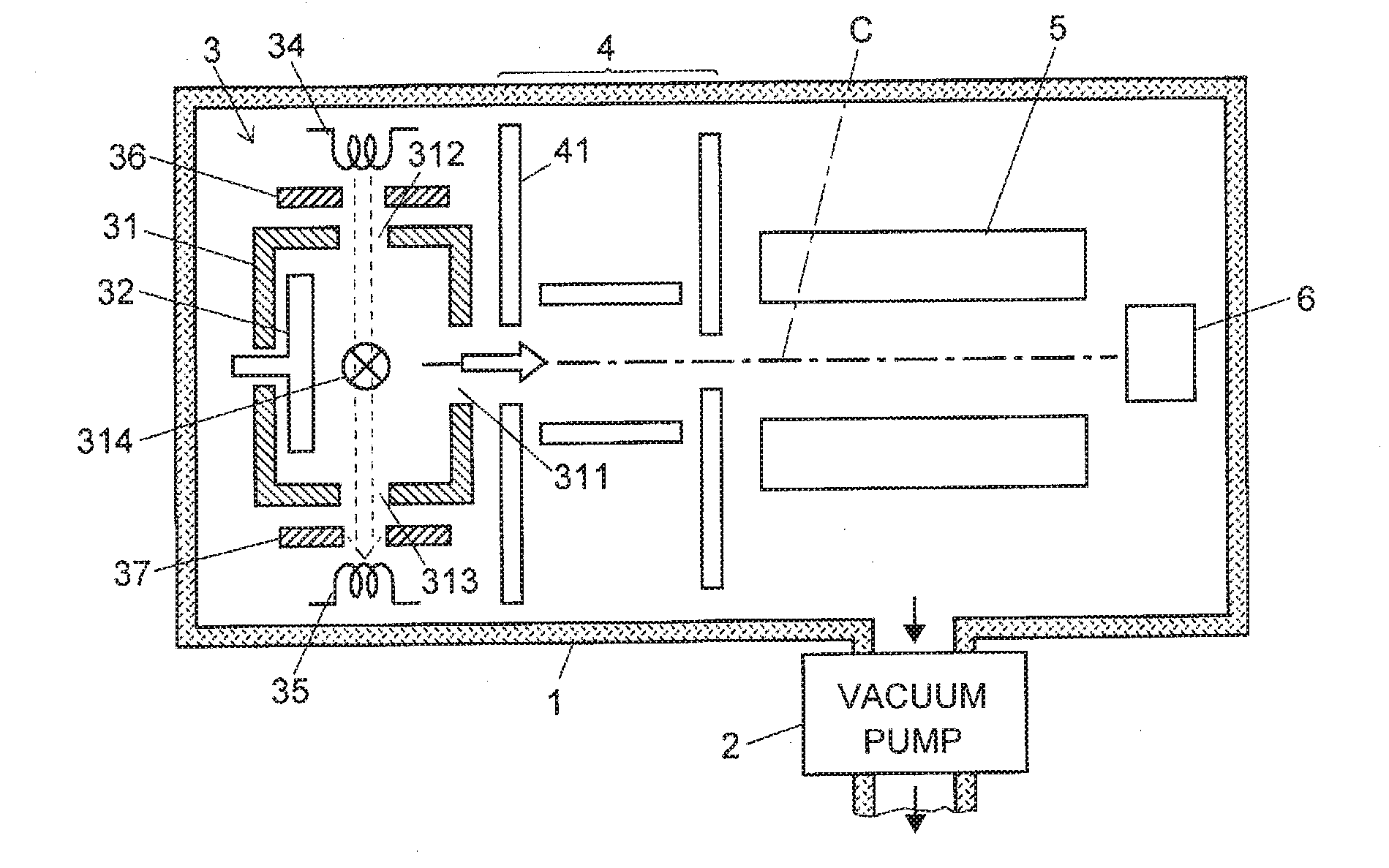
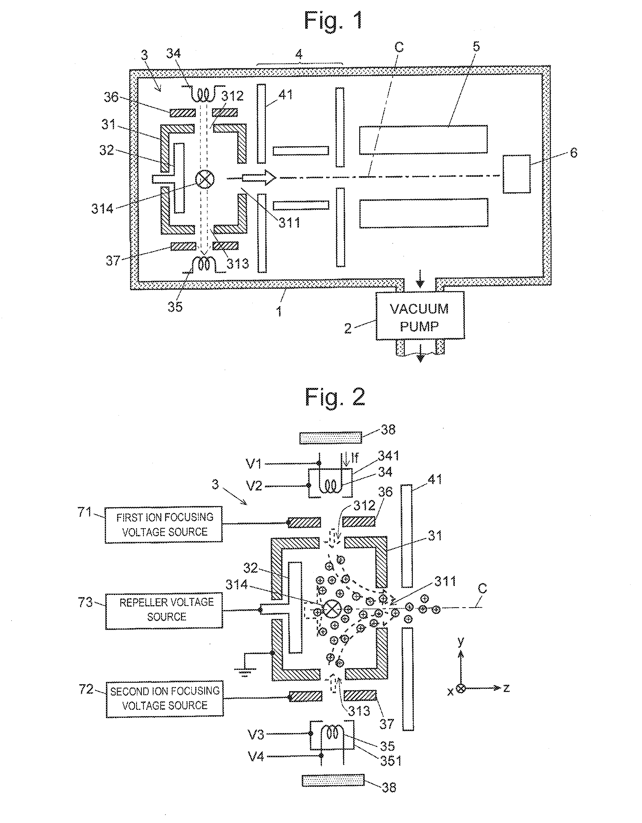
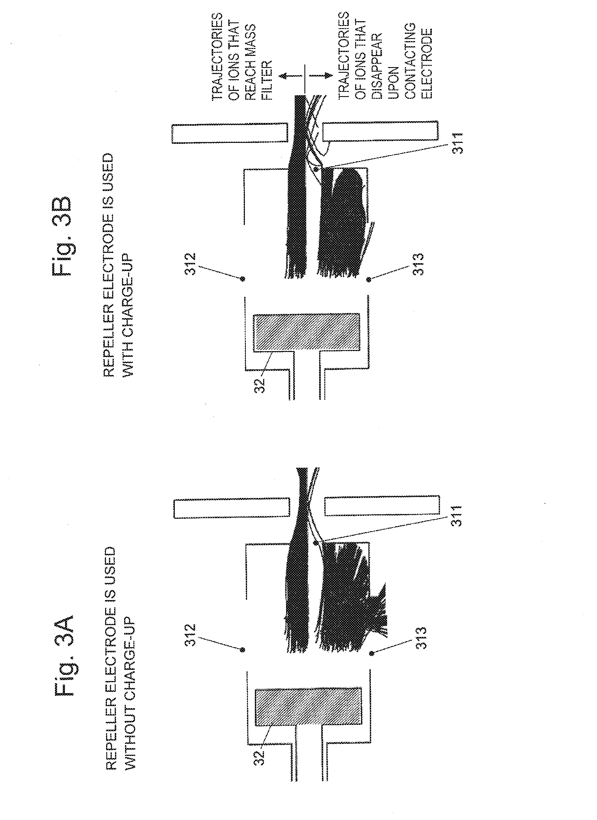
[0036]An ion source according to an embodiment of the present invention is described with reference to the attached drawings. FIG. 1 is a schematic configuration diagram of a mass spectrometer using the ion source according to the present embodiment, and FIG. 2 is a configuration diagram of the ion source according to the present embodiment. The same constituent elements as those in the conventional ion sources that have already been described with reference to FIG. 6 and FIG. 7 are denoted by the same reference signs.

[0037]First, the mass spectrometer using the ion source of the present embodiment is described with reference to FIG. 1. An ion source 3, an ion transport optical system 4, a quadrupole mass filter 5 as a mass analyzer, and an ion detector 6 are arranged inside of a chamber 1 that is evacuated by a vacuum pump 2. For example, a sample gas that flows out from a column of a gas chromatograph (not illustrated) is communicated with a sample introduction port 314 of an ioni...


PUM


Abstract

In an ion source 3 in which a repeller electrode 32 for forming a repelling electric field that repels ions toward an ion emission port 311 is provided inside of an ionization chamber 31, ion focusing electrodes 36 and 37 are respectively arranged between an electron introduction port 312 and a filament 34 and between an electron discharge port 313 and a counter filament 35. An electric field formed by applying a predetermined voltage to each of the ion focusing electrodes 36 and 37 intrudes into the ionization chamber 31 through the electron introduction port 312 and the electron discharge port 313, and becomes a focusing electric field that pushes the ions in an ion optical axis C direction. Ions at positions off a central part of the ionization chamber 31 receive the combined force of the force of the repelling electric field and the force of the focusing electric field, and move toward the ion emission port 311 while approaching the ion optical axis C. Accordingly, the amount of ions sent out from the ion emission port increases. Further, even if a charge-up phenomenon occurs, the ion trajectories less easily change, and the stability of the sensitivity can be enhanced.

Description

TECHNICAL FIELD[0001]The present invention relates to an ionization apparatus for ionizing sample molecules and atoms, and, more specifically, relates to an ionization apparatus using thermal electrons according to an electron ionization (EI) method, a chemical ionization (CI) method, and other such methods. The ionization apparatus according to the present invention can be used as, for example, an ion source of a mass spectrometer, and can also be used for various apparatuses using ions such as an ion implantation apparatus.BACKGROUND ART[0002]When a gas sample is ionized in a mass spectrometer, an ionization method using thermal electrons, such as an electron ionization method and a chemical ionization method, is generally used. FIG. 6 and FIG. 7 are configuration diagrams of conventional general EI ion sources. Although an example case where positive ions are analyzed is described here, even in the case where negative ions are to be analyzed, a basic operation is the same except ...

Claims


Application Information

Patent Timeline
Patent Type & Authority Applications(United States)
IPC IPC(8): H01J49/14
CPCH01J27/024H01J27/205H01J49/147H01J49/145H01J49/067H01J49/10
Inventor TATEISHI, YUSUKETAKAHASHI, KAZUTERUSATO, HIDEKI
Owner SHIMADZU CORP
Why Eureka
Try Eureka