Photogrammetry system and photogrammetry method
- Summary
- Abstract
- Description
- Claims
- Application Information
AI Technical Summary
Benefits of technology
Problems solved by technology
Method used
Image
Examples
embodiment 1
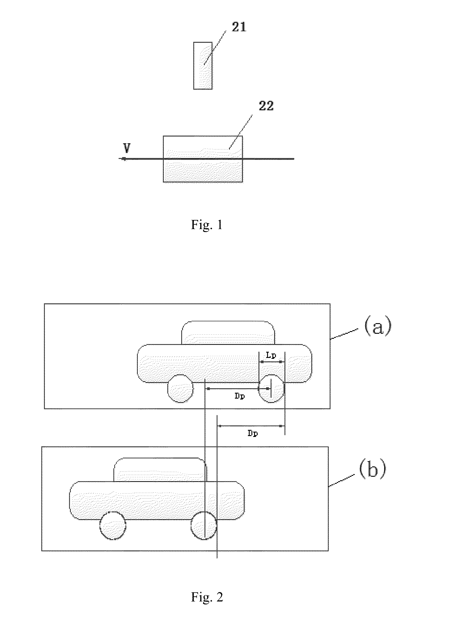
[0107]FIG. 1 is a schematic diagram of embodiment 1 of a photogrammetry system of the present invention. As shown in FIG. 1, in the embodiment 1, the photographing devices are cameras, an object moves in a direction of arrow in FIG. 1 (i.e., a leftward direction in FIG. 1), and the object is photographed by the cameras disposed around a movement pathway of the object. Preferably, the cameras are vertical to the direction of movement of the object (that is, the cameras photograph the object in a direction vertical to the direction of movement of the object), but the present invention is not limited thereto. The cameras may also be arranged according to the requirements for installation convenience and measurement of the system.
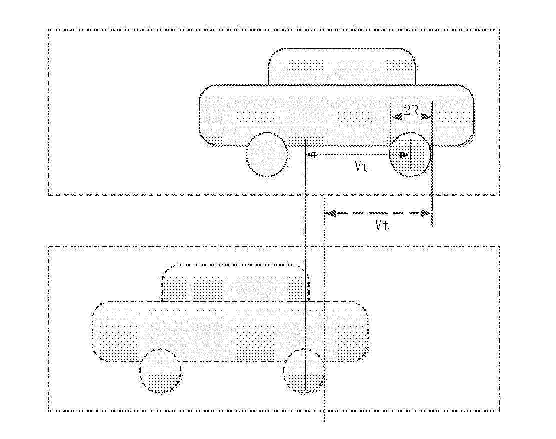
[0108]During measurement, the cameras photograph the moving object for two times at a predetermined time interval t. In the case where the movement speed V of the object is known (including the case where the movement speed V of the object may be measured by th...
embodiment 2
[0114]Embodiment 1 shows a self-adaptive measurement solution which may measure the speed of a moving object, the length of an object or a component thereof and the time interval. In contrast, this embodiment may adaptively measure the length of a static object.
[0115]According to the relativity of movement, an object is static, and a camera is moved at a speed −V (in a reverse direction of V), which is actually equivalent to the movement of embodiment 1. Accordingly, the length of the static object or a portion of the object may be measured by the same method.
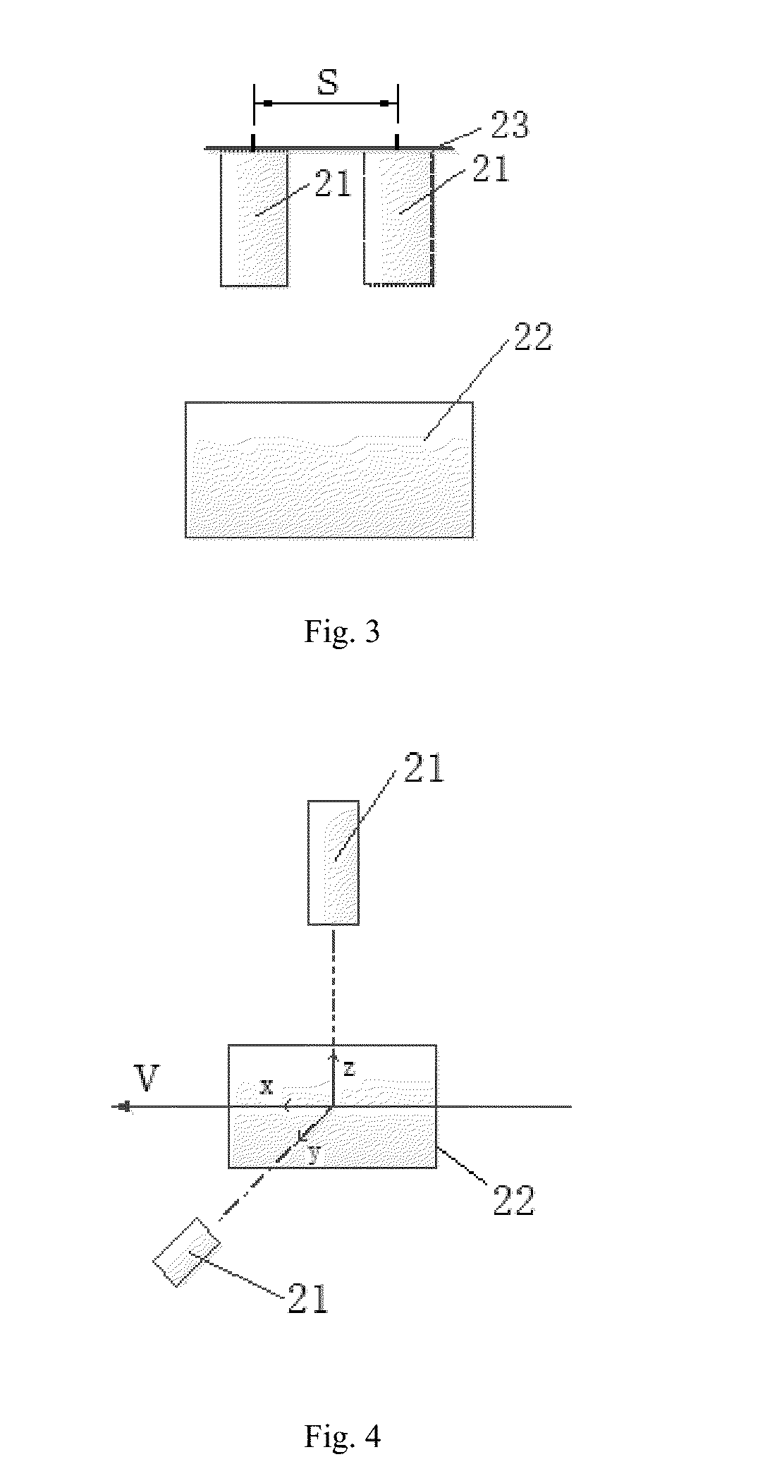
[0116]In this embodiment, to further simplify the system, Vt in the formula (1) is equal to a distance interval of two times of photographing (i.e., a distance of movement of the camera during two times of photographing). The distance interval of the camera during two times of photographing may be set as S, a relative distance difference of the object in the pictures is Dp and the length of the object or a portion of the object...
embodiment 3
[0121]In practical applications, to solve the measurement of the size in a three-dimensional direction, many methods may be taken into consideration, for example, using a 3D camera. For example, laser ranging or others are combined with the present invention.
[0122]However, in this embodiment, to further develop the self-adaptive photogrammetry solution of embodiment 1 and embodiment 2, as shown in FIG. 4, a set of camera of embodiment 1 (or embodiment 2) is disposed in another direction, so as to complete the measurement of the size in a third dimension. Preferably, the two cameras are vertical to each other. For example, as shown in FIG. 4, one of the cameras photographs along z-axis, while the other one photographs along y-axis. Then, the size of an object is measured according to the pictures obtained by photographing in the two directions.
[0123]Moreover, in a further simplified solution, the camera for photographing along the y-axis in FIG. 4 only photographs once, so that the s...
PUM
 Abstract
Description
Claims
Application Information
 - R&D
- Intellectual Property
- Life Sciences
- Materials
- Tech Scout
- Unparalleled Data Quality
- Higher Quality Content
- 60% Fewer Hallucinations
Browse by: Latest US Patents, China's latest patents, Technical Efficacy Thesaurus, Application Domain, Technology Topic, Popular Technical Reports.
© 2025 PatSnap. All rights reserved.Legal|Privacy policy|Modern Slavery Act Transparency Statement|Sitemap|About US| Contact US: help@patsnap.com


