
Smart sensor devices for measuring and verifying solar array performance

a solar array and sensor technology, applied in the field of solar array monitoring systems, can solve the problems of high cost, limited weather monitoring hardware systems for monitoring the efficiency of solar systems, and are almost non-existent in residential and small commercial applications. to achieve the effect of gauging the performance of solar energy systems

Active Publication Date: 2016-09-01
POWEROWNERS
View PDF4 Cites 5 Cited by
  • Summary
  • Abstract
  • Description
  • Claims
  • Application Information

AI Technical Summary

Benefits of technology

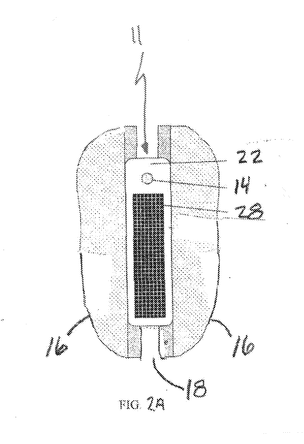
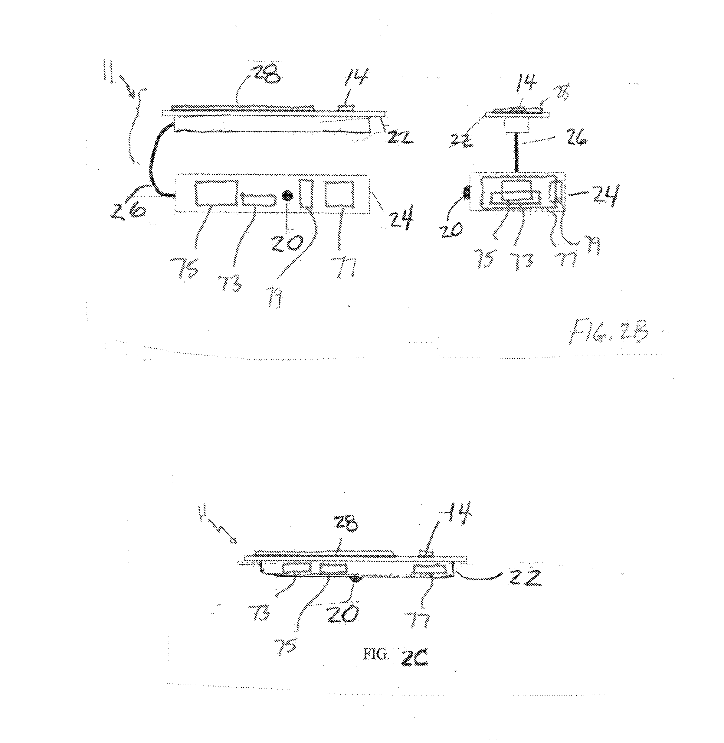
Embodiments of the present invention provide smart sensor devices that can better measure the performance of solar energy systems. These devices can also help to simulate the output of solar energy systems. Additionally, the invention includes methods for using and controlling these smart sensor devices. The invention can help utilities manage power distribution more efficiently. The smart sensor devices operate by sensing and processing environmental data, and transmitting this data at a frequency that is proportional to the expected level of sun exposure. This results in a more frequent transmission during times when sun exposure is expected to be intense, and a less frequent transmission during times when sun exposure is expected to be less intense.

Problems solved by technology

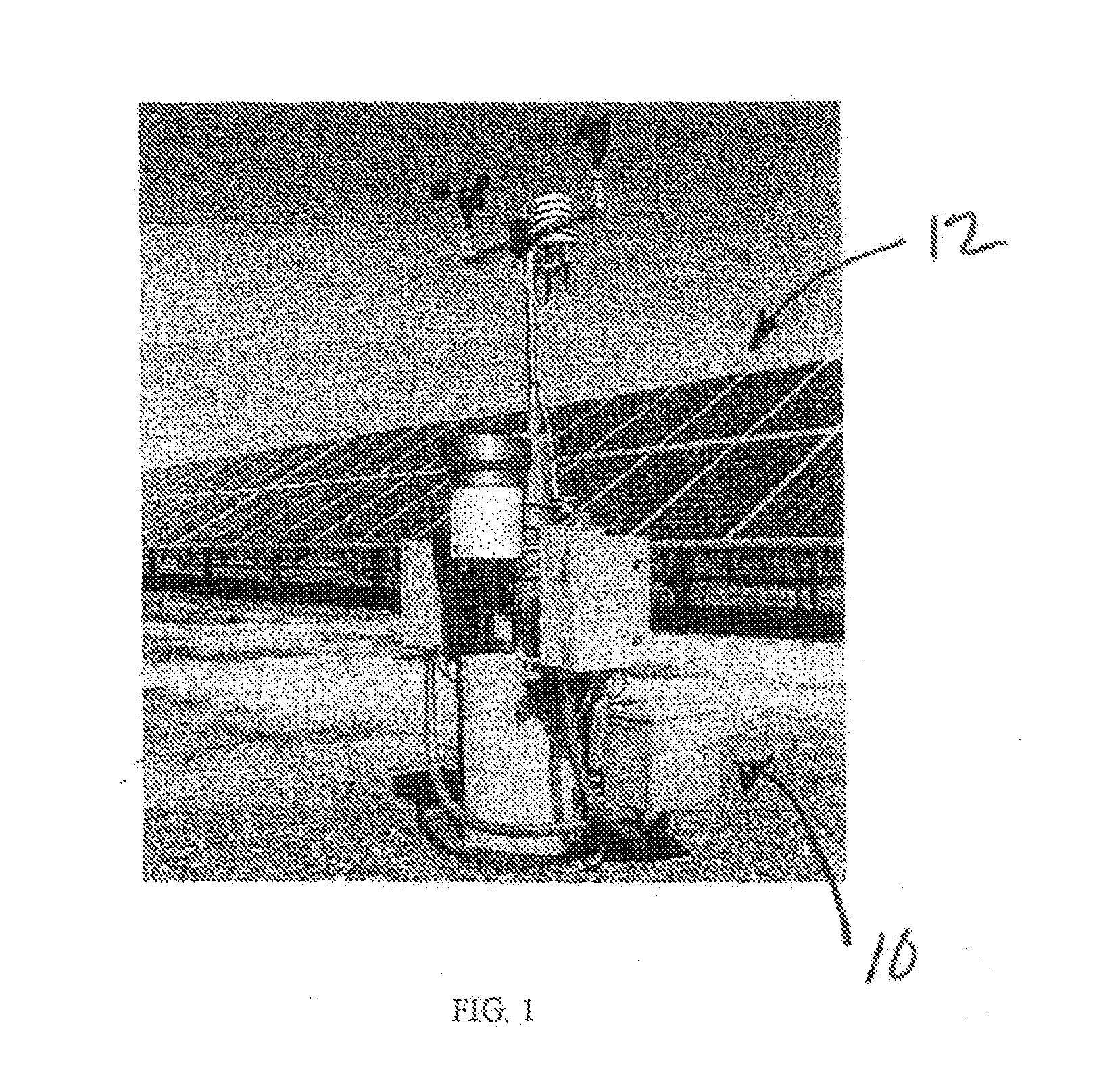
Referring to FIG. 1, traditional weather monitoring hardware systems for monitoring efficiency of solar systems experience limitations due to high cost, non-standardized installation and operations, and inconsistent performance calculations and methods.
Limitations of such weather stations include high cost, making them almost non-existent in residential and small commercial applications due to price factors, non-standardization, meaning that vendors install and configure these units in non-standardized ways, and lack of packaging that accounts for real-world conditions such as snow and dirt.

Method used


Image

  • Smart sensor devices for measuring and verifying solar array performance
  • Smart sensor devices for measuring and verifying solar array performance
  • Smart sensor devices for measuring and verifying solar array performance

Examples


Embodiment Construction

[0118]Various exemplary embodiments will be described more fully hereinafter with reference to the accompanying drawings, in which some exemplary embodiments are shown. The present inventive concepts may, however, be embodied in many different forms and should not be construed as limited to the exemplary embodiments set forth herein.

[0119]It will be understood that when an element or layer is referred to as being “on,”“connected to” or “coupled to” another element or layer, it can be directly on, connected or coupled to the other element or layer or intervening elements or layers may be present. In contrast, when an element is referred to as being “directly on,”“directly connected to” or “directly coupled to” another element or layer, there are no intervening elements or layers present. Like numerals refer to like elements throughout. As may be used herein, the term “and / or” includes any and all combinations of one or more of the associated listed items.

[0120]It will be understood t...


PUM


Abstract

A device comprises a platform constructed and arranged to be mounted to one or more solar array modules and one or more solar irradiance sensors on the platform configured to receive incident solar energy, the solar irradiance sensors oriented on the platform so that the received incident solar energy is comparable to that received by the solar array modules, the one or more solar irradiance sensors providing solar irradiance signals in response to the incident solar energy. A processor is on the platform, the processor configured to receive the solar irradiance signals and, in response, generating a performance reference metric based on the solar irradiance signals, the performance reference metric related to the expected performance of the one or more solar array modules to which the platform is mounted. A transmitter is on the platform, the transmitter configured to periodically transmit the performance reference metric to a receiver.

Description

CROSS-REFERENCE TO RELATED APPLICATION[0001]This application claims priority to and the benefit of U.S. Provisional Patent Application No. 61 / 904,169, filed on Nov. 14, 2013, the entire content of which is incorporated by reference herein.BACKGROUND[0002]1. Technical Field[0003]The present disclosure relates to monitoring systems for solar and energy systems, and, more particularly, to a smart sensor device for a solar system, a system that incorporates the smart sensor device, and operational methods for gauging performance of, or simulating the output of, solar energy systems.[0004]2. Discussion of Related Art[0005]Referring to FIG. 1, traditional weather monitoring hardware systems for monitoring efficiency of solar systems experience limitations due to high cost, non-standardized installation and operations, and inconsistent performance calculations and methods. Traditional weather stations typically are large standalone structures 10 located at positions away from the solar arr...

Claims


Application Information

Patent Timeline
IPC IPC(8): H02S50/00G01K13/00G01J1/44
CPCH02S50/00G01J1/44G01J2001/4276G01J2001/4285G01K13/00Y02E10/47F24S50/20F24S2201/00Y02E10/50
Inventor LEARY, DANIEL P.GREENWOOD, ROY S.
Owner POWEROWNERS
Learn More