Air filter monitoring

a technology of air filter and monitoring device, which is applied in the installation of electric equipment, instruments, cleaning equipment, etc., can solve the problems of filter clogging after some time of use, difficult to perceive phenomena by users, and vacuum cleaners, and achieve the effect of reliable flow prediction

Active Publication Date: 2016-09-08
KONINKLJIJKE PHILIPS NV
View PDF4 Cites 4 Cited by
  • Summary
  • Abstract
  • Description
  • Claims
  • Application Information

AI Technical Summary

Benefits of technology

[0013]A combination of measuring a pressure difference over the fan, and the motor cur

Problems solved by technology

Vacuum cleaners have the disadvantage that filters will get clogged after some time of use.
This phenomenon is hard to perceive by users, because the pollution of the filters is a slow process.
In normal use it can take more than half a year before the performance of the vacuum cleaner is impaired.
The disadvantage of this principle is that, at varying flow, the pressure difference does not rel

Method used


Image

  • Air filter monitoring
  • Air filter monitoring
  • Air filter monitoring

Examples


Embodiment Construction

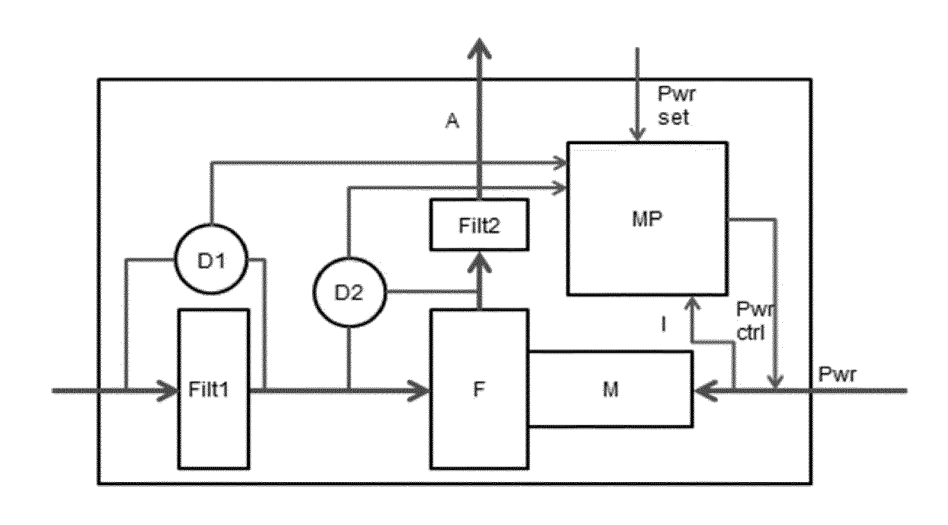
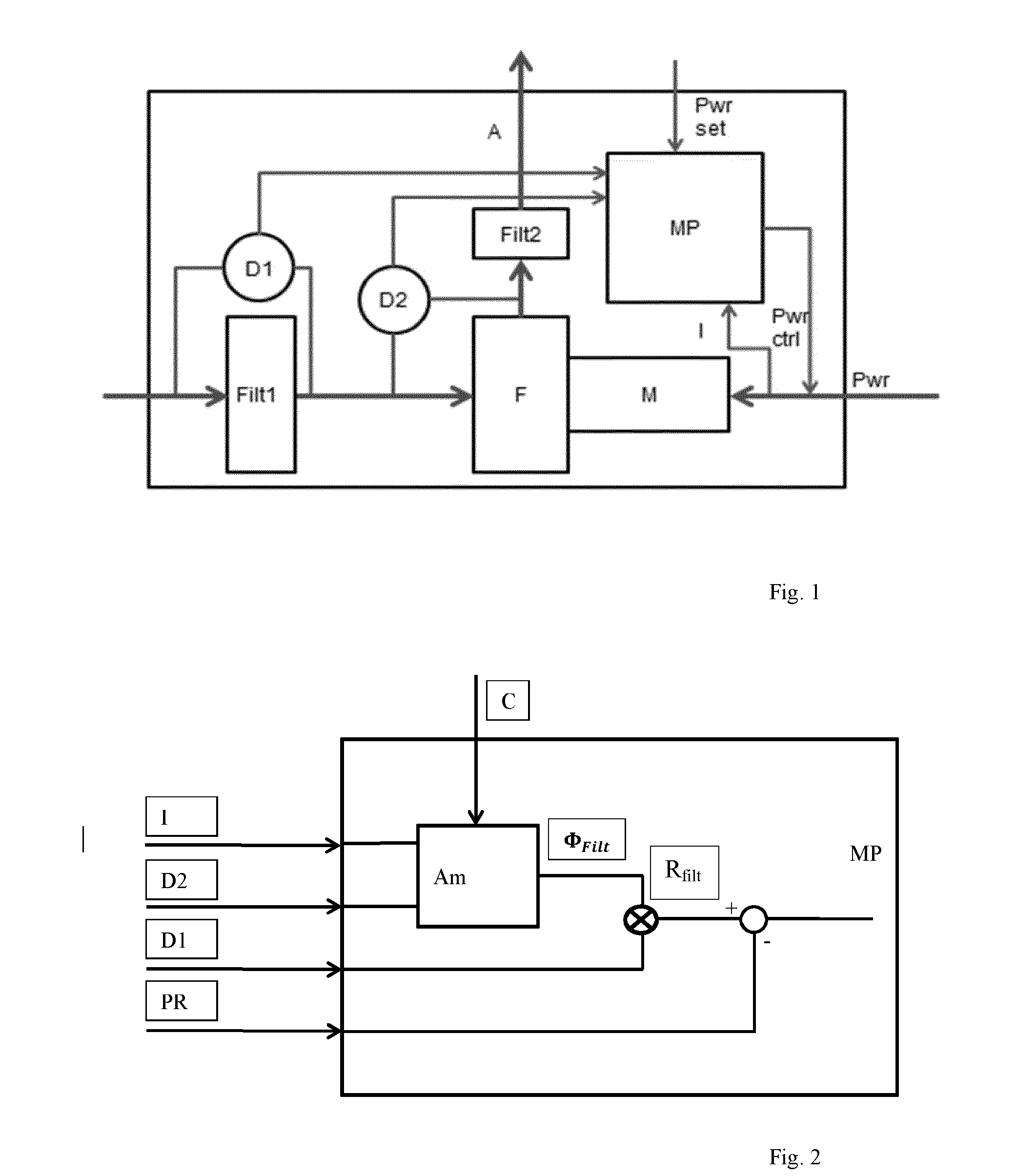
[0019]FIG. 1 shows an embodiment of a device in accordance with the present invention. An air flow A passes a motor filter Filt1, a fan F that is engaged by a motor M receiving an electrical power signal Pwr, and an exhaust filter Filt2. A first pressure difference sensor D1 measures a pressure difference over the motor filter Filt1, and a second pressure difference sensor D2 measures a pressure difference over the fan F. A microprocessor MP receives signals from the pressure difference sensors D1 and D2, as well as a power setting signal Pwr set, the current I through the motor M, so as to produce a power control signal Pwr ctrl for the motor M.

[0020]The invention is based on the following considerations. The filter resistance will increase when the filter gets polluted. The filter resistance can be known by knowing the air flow and the pressure difference over the motor filter Filt1. Measuring only the pressure difference over the filter Filt1 as an indication of the filter pollut...


PUM


Abstract

In a method of monitoring pollution of an air filter (Filt1) in a device in which an air flow (A) generated by a fan (F) engaged by a motor (M) passes the air filter (Filt1), the pollution is determined using data representative of a pressure difference (D2) over the fan (F), a pressure difference (D1) over the air filter, and a motor current (I) to the motor (M). The method comprises the steps of: estimating a flow through the air filter from data representative of the pressure difference (D2) over the fan (F), and the motor current (I) to the motor (M), estimating a filter resistance of the air filter from data representative of the flow through the air filter, and the pressure difference (D1) over the air filter, and estimating the pollution of the air filter from data representative of the filter resistance of the air filter.

Description

FIELD OF THE INVENTION[0001]The invention relates to a device (e.g. a vacuum cleaner or an air cleaner) comprising an air filter, and to a method of air filter monitoring.BACKGROUND OF THE INVENTION[0002]Vacuum cleaners have the disadvantage that filters will get clogged after some time of use. This phenomenon is hard to perceive by users, because the pollution of the filters is a slow process. In normal use it can take more than half a year before the performance of the vacuum cleaner is impaired.[0003]Some vacuum cleaners are equipped with a pressure switch, measuring the pressure difference over a filter. The disadvantage of this principle is that, at varying flow, the pressure difference does not relate directly to the filter pollution. When lowering the flow by changing the setting of the speed regulator, the pressure difference will decrease and thus the signal generated by the pressure switch might change from ‘polluted’ to ‘clean’, whereas the filter pollution has not change...

Claims


Application Information

Patent Timeline
IPC IPC(8): A47L9/19G01N15/08A47L9/28
CPCA47L9/19G01N2015/084G01N15/0826A47L9/2842
Inventor KUPERUS, JOHAN BERNARDVAN DER KOOI, JOHANNES TSEARDDE WIT, BASTIAAN JOHANNES
Owner KONINKLJIJKE PHILIPS NV
Why Eureka
Try Eureka