Distributed Motor Torque Generation System and Method of Control

a technology of distributed motor and torque generation, which is applied in the direction of electric devices, propulsion by batteries/cells, transportation and packaging, etc., can solve the problems of not monitoring the steering angle, front wheels, however, do not receive different amounts of torque, and vehicles do not respond immediately, etc., to achieve fast acceleration and deceleration, reduce cost and power consumption, and reduce the effect of motor siz

Inactive Publication Date: 2016-09-15
R MOTOR
View PDF3 Cites 26 Cited by
  • Summary
  • Abstract
  • Description
  • Claims
  • Application Information

AI Technical Summary

Benefits of technology

[0047]It is known that Vector motor control or field-oriented control provides control over three-phase AC electric motors by adjusting the output current of a VFD inverter in Voltage magnitude and Frequency. FOC is a control technique that is used in AC synchronous and induction motor applications that was originally developed for high-performance motor applications which can operate smoothly over the full speed range, can generate full torque at zero speed, and is capable of fast acceleration and deceleration but that is becoming increasingly attractive for lower performance applications as well due to FOC's motor size, cost and power consumption reduction superiority. Not only is FOC very common in induction motor control applications due to its traditional superiority in high-performance applications, but the expectation is that it will eventually nearly universally displace single-variable scalar volts-per-Hertz (V / f) control.

Problems solved by technology

A rear-wheel drive torque vectoring differential works the same way as a front-wheel drive differential, but doesn't monitor the steering angle.
The front wheels, however, do not receive different amounts of torque.
The vehicle does not, however, respond immediately because tires take time to build up lateral forces, and the actual vehicle response may not be exactly what is required, or expected.
At very high speeds, or if the vehicle's suspension is poorly tuned or the operator poorly skilled, the oscillations can increase and the vehicle can go out of control.
Even at lower speeds, the oscillations can make the vehicle feel less stable and the driver may need to make multiple steering adjustments to successfully follow the intended path.
Conventional vehicle suspension is tuned through bump steer, static settings, etc, to minimize the oscillations and to give a stable response at all vehicle speeds and loading conditions, but any increase in stability is at the expense of vehicle agility and the vehicle response can become disappointing.
a. Increasing torque on the one side must be balanced by a reduction on the other side to avoid unnecessary acceleration.
b. Vertical load on each wheel—particularly as the vehicle corners,
c. the vertical load on the inner wheels reduce and drive / braking torque may cause wheel spin or wheel lock-up.
c. The addition of drive or braking torques at the rear may result in loss of rear grip—leading to loss of control.
Therefore, simply distributing the torque based on steering wheel angle would achieve more yaw response (for the same steering input), but it may not create any improvement in stability.
The measured yaw rate is then used as feedback, giving a yaw error.
A limitation to conventional feedback control is that the system relies on measured yaw rate as an input signal.
This unfortunately creates a time delay in the signal, and the feedback becomes too late creating overshoot and oscillations in the response.

Method used


Image

  • Distributed Motor Torque Generation System and Method of Control
  • Distributed Motor Torque Generation System and Method of Control
  • Distributed Motor Torque Generation System and Method of Control

Examples


Embodiment Construction

[0056]Reference will now be made to the drawings to describe various aspects of exemplary embodiments of the invention. It should be understood that the drawings are diagrammatic and schematic representations of such exemplary embodiments and, accordingly, are not limiting of the scope of the present invention, nor are the drawings necessarily drawn to scale.

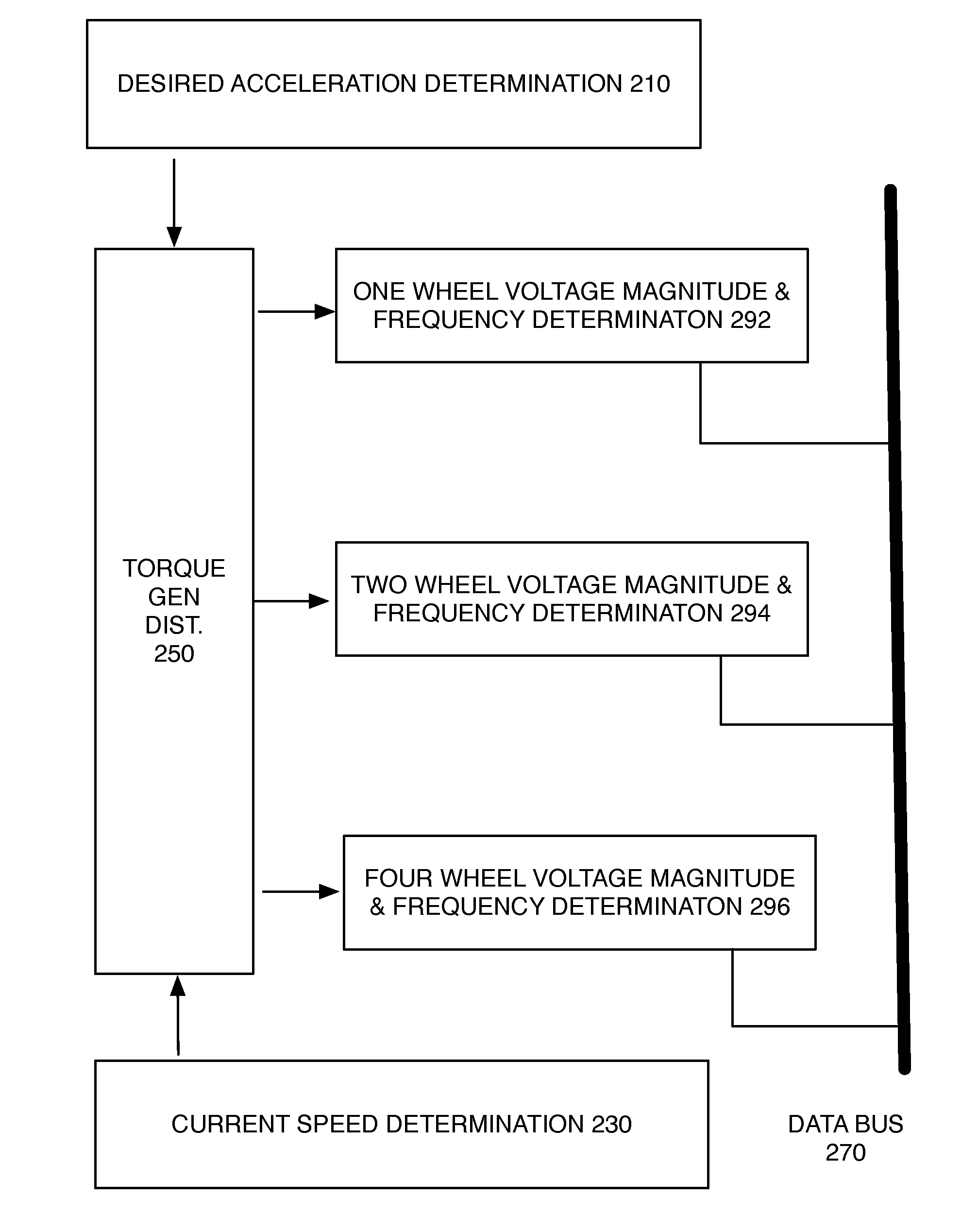
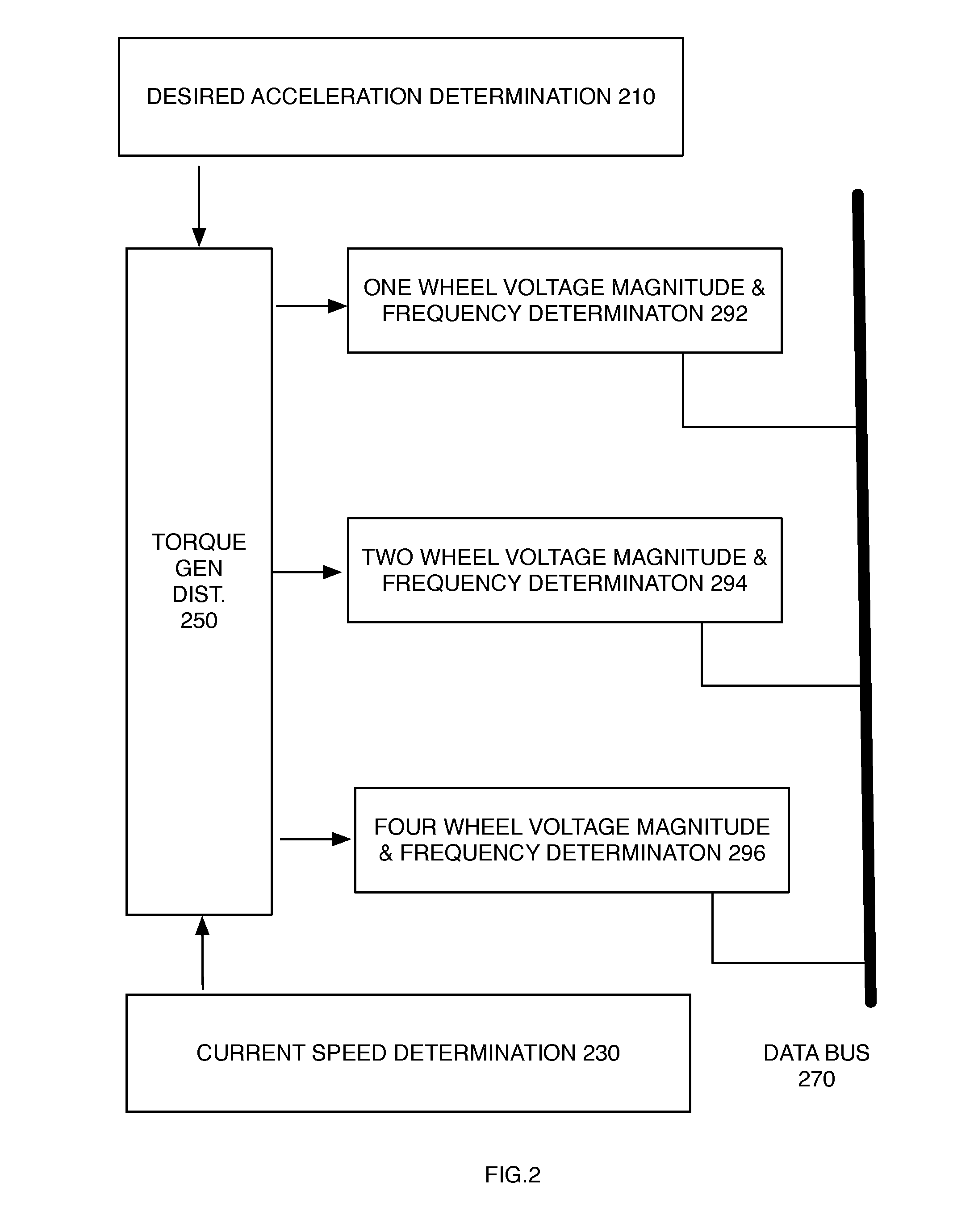
[0057]Referring now to FIG. 2, an embodiment of an apparatus for controlling voltage magnitude and voltage frequencies at one or more AC motors. A one wheel determination circuit 292 is coupled to a data bus 270. A two wheel determination circuit 294 is coupled to the data bus 270. A four wheel determination circuit 296 is coupled to the data bus 270. Depending on the determination of the torque generation distribution circuit 250, the addressable Adaptive Field-Oriented Control circuits associated with each AC motor will receive a digital indicia of voltage magnitude and voltage frequency to be provided to their respective atta...


PUM


Abstract

An apparatus for an electrically powered terrestrial vehicle applies electrical energy to front wheels and to rear wheels. A control system receives desired acceleration inputs and provides target torque requirements to a plurality of adaptive field-oriented motor control circuits. One or more three-phase alternating current synchronous motors receive voltage magnitude and voltage frequency to generate torque, which is applied through a reduction gear. One motor only may be powered during certain modes of operation.

Description

CROSS-REFERENCES TO RELATED APPLICATIONS[0001]This application benefits from Ser. No. 61 / 950,229 filed 10 Mar. 2014 “Adaptive Torque Budgeting and Electric Motor Control System” which is incorporated by reference in its entirety and receives the priority date thereof.[0002]This application is a continuation in part of Ser. No. 14 / 499,203 filed Sep. 28, 2014.STATEMENT REGARDING FEDERALLY SPONSORED RESEARCH OR DEVELOPMENT[0003]Not ApplicableTHE NAMES OF THE PARTIES TO A JOINT RESEARCH AGREEMENT[0004]Not ApplicableINCORPORATION-BY-REFERENCE OF MATERIAL SUBMITTED ON A COMPACT DISK OR AS A TEXT FILE VIA THE OFFICE ELECTRONIC FILING SYSTEM (EFS-WEB)[0005]Not ApplicableSTATEMENT REGARDING PRIOR DISCLOSURES BY THE INVENTOR OR A JOINT INVENTOR[0006]Not ApplicableBACKGROUND OF THE INVENTION[0007]1. Technical Field[0008]The field of the invention is within motor vehicles, and more specifically the control over distribution of torque generation by a plurality of electric motors located througho...

Claims


Application Information

Patent Timeline
Patent Type & Authority Applications(United States)
IPC IPC(8): B60L15/20B60L15/02B60W30/045H02P5/747
CPCB60L15/2045B60W2720/40B60L15/2036B60L15/025B60W30/045B60L2220/46B60L2240/465B60L2240/463B60L2260/28B60W2550/14B60W2550/12B60W2540/30B60W2520/06B60W2520/105B60W2710/083H02P5/747B60L3/102B60L3/106B60L2240/423B60L2240/427B60K7/0007B60K17/043B60K17/356B60L2240/22B60L50/51Y02T10/64Y02T10/72Y02T10/70B60W2552/00B60W2555/20
Inventor DRAKO, DEAN
Owner R MOTOR
Why Eureka
Try Eureka