Correcting for aberrations in incoherent imaging systems using fourier ptychographic techniques

Active Publication Date: 2016-09-15
CALIFORNIA INST OF TECH
View PDF1 Cites 45 Cited by
  • Summary
  • Abstract
  • Description
  • Claims
  • Application Information

AI Technical Summary

Benefits of technology

The patent text describes a method and system for correcting aberrations in images captured using incoherent imaging techniques. The method involves sequentially acquiring coherent images of a specimen from different angles while shining a coherent light onto it. These images are then combined to create an improved resolution image and estimate the pupil function of the imaging system. Using these estimates, the optical transfer function of the system is determined and an aberration-corrected incoherent image is generated by removing the aberration through a deconvolution process. The technical effect of this patent is improved accuracy and resolution in incoherent imaging, allowing for better analysis and interpretation of the captured images.

Problems solved by technology

The standard EPRY method cannot be used directly to correct for the spatially-varying aberration in a captured fluorescence image since the standard EPRY method is designed primarily for a coherent imaging system.
Due to limitations of the physical lens design, imaging systems tend to exhibit aberrations that vary across their field-of-view (FOV).
For wide FOV imaging devices, aberrations significantly deteriorate image quality near the FOV boundary.
The standard EPRY method cannot be directly applied to improve fluorescence imaging because both FP technique and EPRY methods are based on coherent imaging schemes.
Unlike the coherent transfer function, the Hm(fx,fy), also known as the optical transfer function (OTF), can have numerous zeros within its bandpass and its values are very low near the bandpass's edges, which means that the sample information may be lost or overwhelmed by noise at these spatial frequencies.
Due to the nature of the OTF, inverting Eqn. 3 to solve for Om(fx,fy) may be an ill-posed problem.
While it is reasonable to assume Nm(fx,fy) is white Gaussian noise, Om(fx,fy) is hard to determine without some prior knowledge of the sample's spatial distribution.
Interference filters are coated with multiple layers of different indices of refraction to constructively interfere the desired wavelength and allow it through while destructively interfere the unwanted wavelengths and reflect them back.
In the Fourier domain, Eqn. 2 is represented as Eqn. 3. Unlike the coherent transfer function, the Hm(fx,fy), also known as the optical transfer function (OTF), can have numerous zeros within its bandpass and its values are very low near the bandpass's edges, which means that the sample information may be lost or overwhelmed by noise at these spatial frequencies.
Due to the nature of the OTF, inverting Eqn. 3 to solve for om(fx,fy) may be an ill-posed problem.
While it is reasonable to assume Nm(fx,fy) is flat, white Gaussian noise Om(fx,fy) is hard to determine without some prior knowledge of the sample's spatial distribution.
The raw fluorescence image captured is severely blurred because it is captured near the edge of the imaging system's FOV.
Decreasing exposure times can reduce signal-to-noise ratio which can make the deconvolution method less effective.
Asymmetric aberrations can cause a noticeable lateral shift in the images.
Other deconvolution methods that do not use the pupil function characterized by the FP technique cannot generate a corrected image with the proper lateral shift because the methods do not account for the absolute location of the image, meaning that the deconvolved image can have any arbitrary lateral shift as its solution.
Without the same lateral shift for FPM and fluorescence images, the direct overlay of the images will not have the correct spatial correspondence between them.
Moreover, the separation of various system components in the implementations described above should not be understood as requiring such separation in all implementations.

Method used


Image

  • Correcting for aberrations in incoherent imaging systems using fourier ptychographic techniques
  • Correcting for aberrations in incoherent imaging systems using fourier ptychographic techniques
  • Correcting for aberrations in incoherent imaging systems using fourier ptychographic techniques

Examples


Embodiment Construction

[0021]Embodiments of the present disclosure will be described below with reference to the accompanying drawings.

I. INTRODUCTION

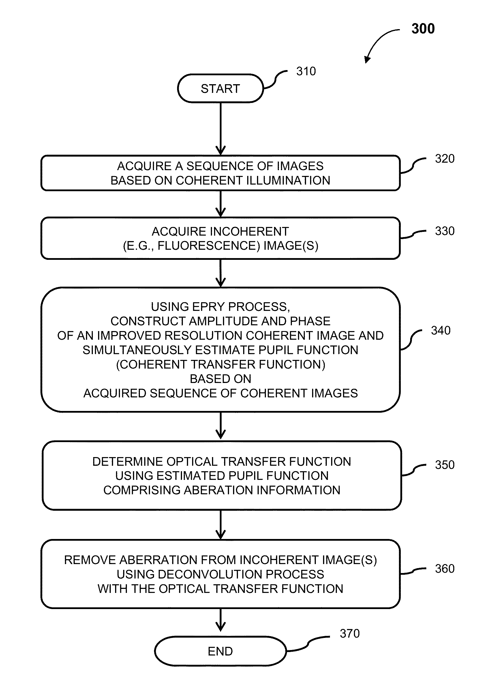
[0022]Recently, an embedded pupil function recovery (EPRY) method was developed in junction with Fourier ptychographic (FP) techniques. The standard EPRY method characterizes a lens' spatially varying aberration and corrects captured images computationally for a coherent imaging setup. Details of this standard EPRY method can be found in G. Zheng, R. Horstmeyer and C. Yang, “Wide-field, high-resolution Fourier ptychographic microscopy,” Nature Photonics, 2013, in X. Ou, G. Zheng and C. Yang, “Embedded pupil function recovery for Fourier ptychographic microscopy,” Optics Express, 2014, which are both hereby incorporated by reference in their entirety. Details of this EPRY method can also be found in U.S. patent application Ser. No. 14 / 572,493 titled “EMBEDDED PUPIL FUNCTION RECOVERY FOR FOURIER PTYCHOGRAPHIC IMAGING DEVICES” and filed on Dec. 16, 2014, which ...


PUM


Abstract

Aberration-corrected incoherent imaging methods and systems that can acquire a sequence of coherent images and an incoherent image of a specimen, implement an embedded pupil function recovery process in junction with Fourier ptychographic technique to construct an improved resolution image and pupil function of the imaging system using the sequence of coherent images, determine an optical transfer function based on the estimated pupil function, and remove the aberration from the incoherent image using a deconvolution process to generate an aberration-corrected incoherent image.

Description

CROSS-REFERENCES TO RELATED APPLICATIONS[0001]This application claims benefit of and priority to U.S. Provisional Patent Application No. 62 / 133,130 titled “Correcting for Aberrations in Incoherent Imaging System via Fourier Ptychographic Microscopy” and filed on Mar. 13, 2015, which is hereby incorporated by reference in its entirety and for all purposes.FIELD[0002]Certain aspects described herein are generally related to imaging methods and systems, and more specifically to methods for aberration correction in incoherent imaging systems using Fourier ptychographic techniques.BACKGROUND[0003]In general, imaging lenses are imperfect in design. Multiple lenses of various shapes and properties are usually intricately combined in an imaging lens to compensate for the deviations from an ideal lens, but this comes at a price of high manufacturing costs and the associated increase in complexity of the lens design. Most lenses available in the market offer a well-resolved image in the regio...

Claims


Application Information

Patent Timeline
IPC IPC(8): G02B21/00
CPCG02B21/0072G02B21/0056G02B21/0076G02B21/008G02B21/0032G02B27/0025
Inventor CHUNG, JAEBUMYANG, CHANGHUEI
Owner CALIFORNIA INST OF TECH
Why Eureka
Try Eureka