Heat pipe temperature management system for a turbomachine

Inactive Publication Date: 2016-10-06
GENERAL ELECTRIC CO
View PDF40 Cites 17 Cited by
  • Summary
  • Abstract
  • Description
  • Claims
  • Application Information

AI Technical Summary

Benefits of technology

The intercooling, aftercooling and cooling systems described in this patent improve the efficiency of compressors and turbines and reduce the amount of steam needed for fuel heating. This results in higher combined cycle heat rates and increased output. The cooler compressor air also reduces temperatures and extends the lifespan of turbine section parts.

Problems solved by technology

However, recompressing the compressed airflow elevates airflow temperature above desired limits.
However, conventional intercoolers are large systems requiring considerable infrastructure and capital costs.
Utilizing low temperature fuel impacts emissions, performance, and efficiency of the gas turbine system.

Method used


Image

  • Heat pipe temperature management system for a turbomachine
  • Heat pipe temperature management system for a turbomachine
  • Heat pipe temperature management system for a turbomachine

Examples


Embodiment Construction

[0030]One or more specific aspects / embodiments of the present invention will be described below. In an effort to provide a concise description of these aspects / embodiments, all features of an actual implementation may not be described in the specification. It should be appreciated that in the development of any such actual implementation, as in any engineering or design project, numerous implementation-specific decisions must be made to achieve the developers' specific goals, such as compliance with machine-related, system-related and business-related constraints, which may vary from one implementation to another. Moreover, it should be appreciated that such a development effort might be complex and time consuming, but would nevertheless be a routine undertaking of design, fabrication, and manufacture for those of ordinary skill having the benefit of this disclosure.

[0031]When introducing elements of various embodiments of the present invention, the articles “a,”“an,” and “the” are ...


PUM


Abstract

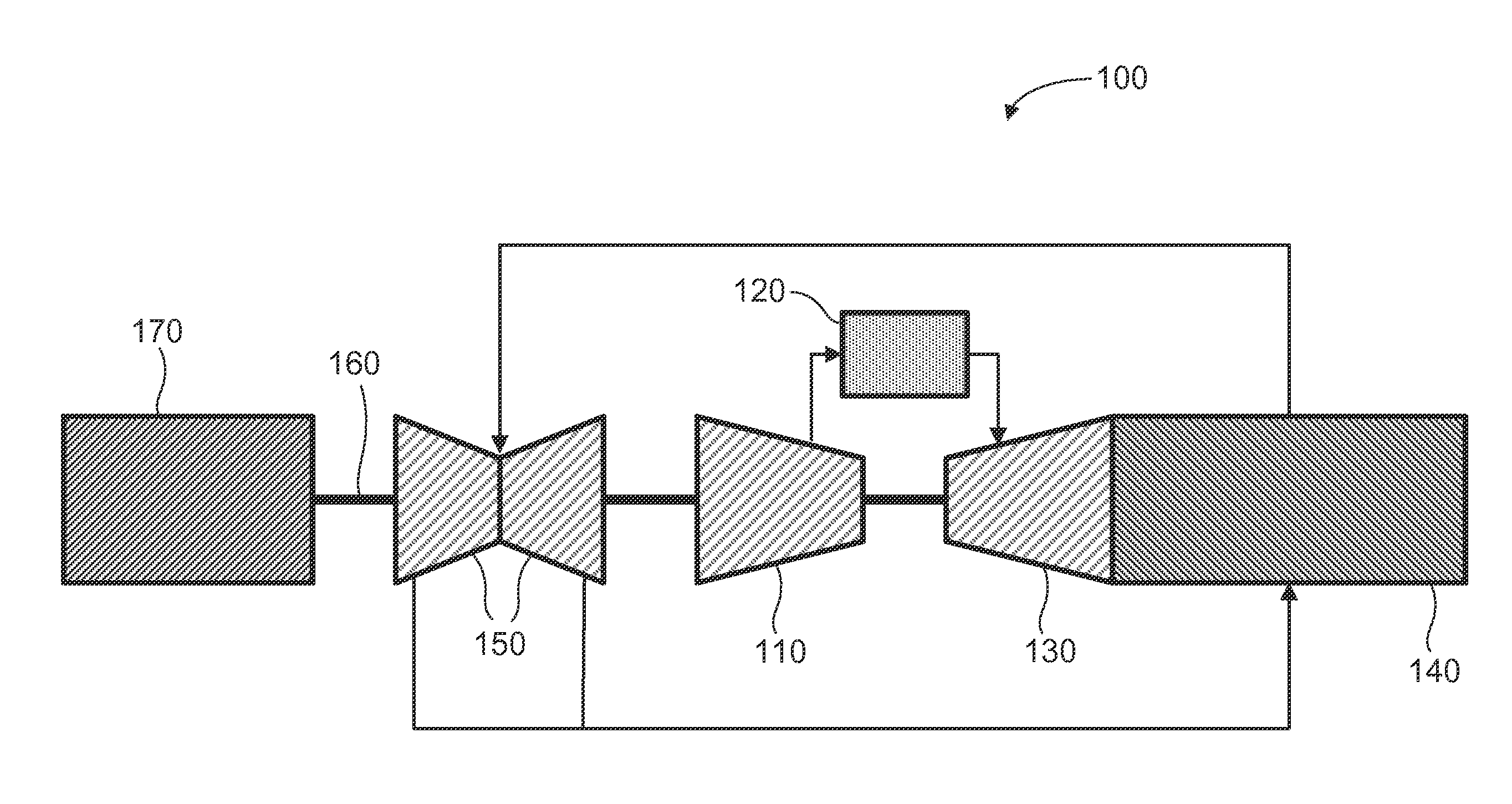
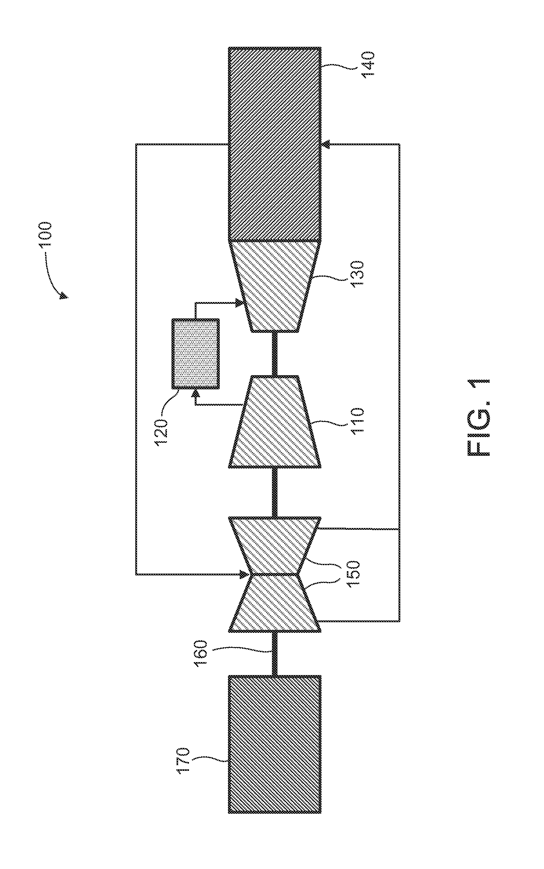
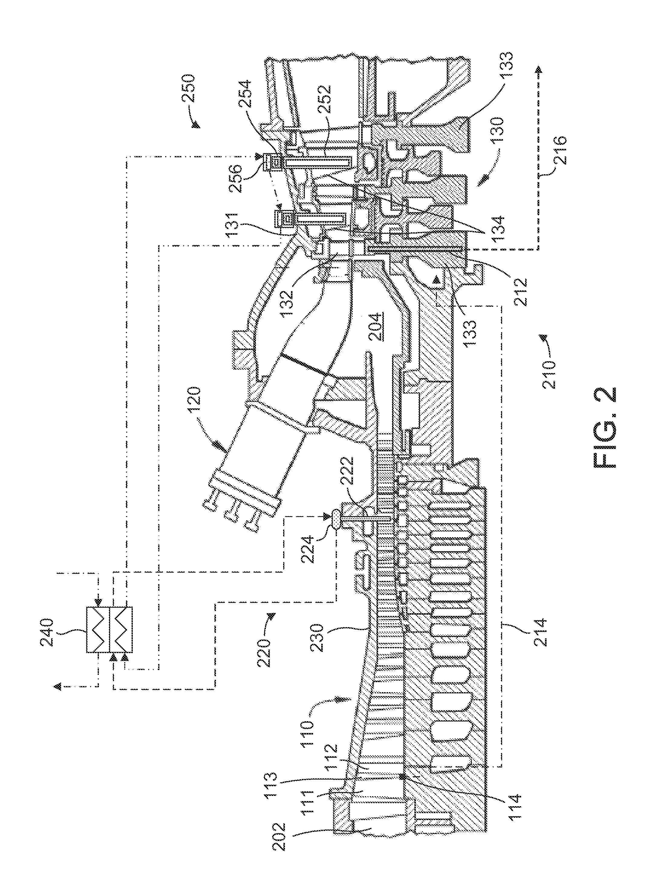
A turbomachine includes a compressor, combustor and a turbine. An intercooler is operatively connected to the compressor. The intercooler includes a first plurality of heat pipes that extend into the inter-stage gap of the compressor, and the heat pipes are operatively connected to a first manifold. The heat pipes and the manifold are configured to transfer heat from the compressed airflow to one or more heat exchangers. A first cooling system is operatively connected to the turbine. The first cooling system includes a second plurality of heat pipes attached to or embedded within at least one of the plurality of wheels. The compressor bleed off air is configured to impinge onto at least one of the plurality of wheels or the second plurality of heat pipes. The second plurality of heat pipes and the compressor bleed off air are configured to cool at least one of the plurality of wheels.

Description

BACKGROUND OF THE INVENTION[0001]Exemplary embodiments of the present invention relate to the art of turbomachines and, more particularly, to a heat pipe intercooler for a turbomachine.[0002]Turbomachines include a compressor operatively connected to a turbine that, in turn, drives another machine such as, a generator. The compressor compresses an incoming airflow that is delivered to a combustor to mix with fuel and be ignited to form high temperature, high pressure combustion products. The high temperature, high pressure combustion products are employed to drive the turbine. In some cases, the compressed airflow leaving the compressor is re-compressed to achieve certain combustion efficiencies. However, recompressing the compressed airflow elevates airflow temperature above desired limits. Accordingly, prior to being recompressed, the airflow is passed through an intercooler. The intercooler, which is between two compressor stages, lowers the temperature of the compressed airflow ...

Claims


Application Information

Patent Timeline
IPC IPC(8): F02C7/18
CPCF02C7/18F01D25/12F02C7/12F01D5/181F01D9/065F01D25/125F01D25/14F02C6/18F02C7/14F02C7/143F02C7/224F05D2260/208
Inventor EKANAYAKE, SANJIMESTRONI, JULIO ENRIQUERIZZO, JOSEPH PAULSCIPIO, ALSTON ILFORDYANG, TIMOTHY TAHTEHWICKERT, THOMAS EDWARD
Owner GENERAL ELECTRIC CO
Why Eureka
Try Eureka