Packaging and termination structure for a solid state battery

a technology of solid-state batteries and packaging, which is applied in the direction of cell components, final product manufacturing, sustainable manufacturing/processing, etc., can solve the problems that skilled in the art have not been able to manufacture thin-film solid-state batteries useful in replacing conventional technology, and achieve accurate encapsulation of the battery device, minimize parasitic mass and volume, and optimize the effect of battery energy density

Active Publication Date: 2016-10-06
SAKTI3
View PDF2 Cites 15 Cited by
  • Summary
  • Abstract
  • Description
  • Claims
  • Application Information

AI Technical Summary

Benefits of technology

[0016]Benefits are achieved over conventional techniques. Depending upon the specific embodiment, one or more of these benefits may be achieved. In a preferred embodiment, the present invention provides a hermetic packaging device for a solid-state battery and a method for making same. In a specific embodiment, the present invention provides a method for forming a self terminated electrode structure configured with a solid state multilayered battery device. In a preferred embodiment, the present invention provides an intrinsically safe packaging device for a solid-state battery and a method for making same. Preferably, the present package and method protects the active components from atmospheric elements and at the same time minimizes the parasitic mass and volume to optimize the battery energy density. Preferably, the present invention includes a method and device for a conformal solid-state package, which can accurately encapsulate a battery device, while protecting the battery electrically, mechanically, and environmentally. Of course, there can be other variations, modifications, and alternatives.

Problems solved by technology
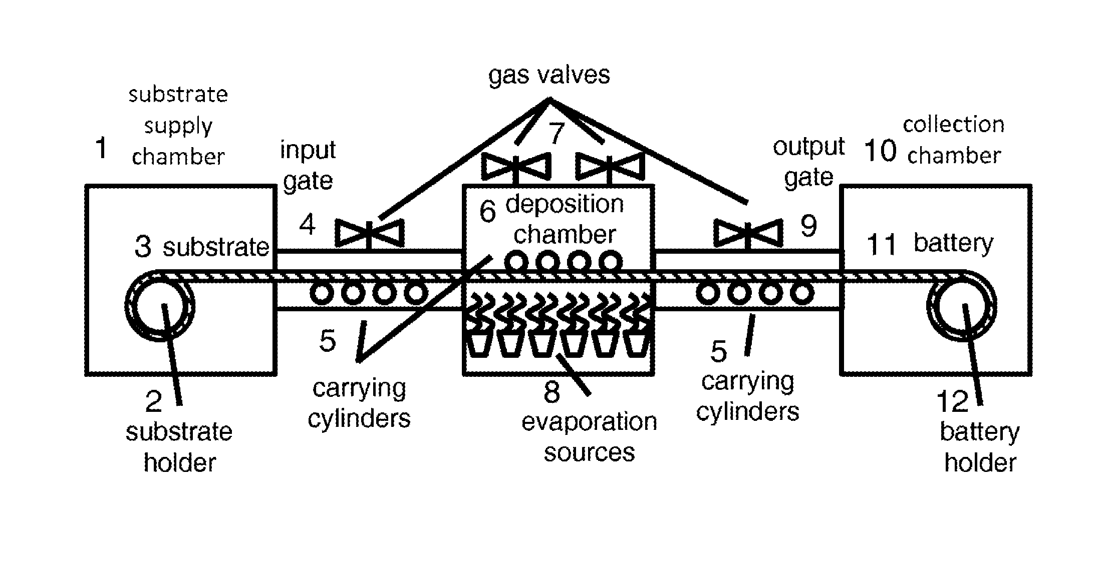
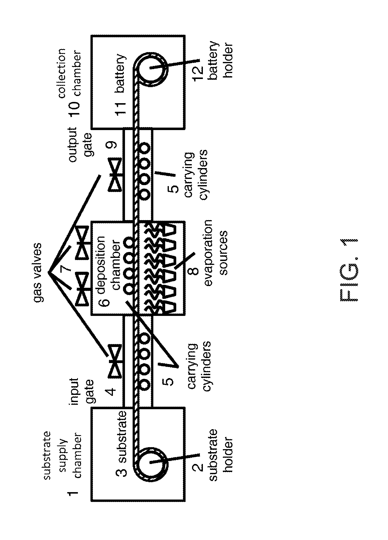
In solid state thin film batteries, those knowledgeable in the field have attempted to build multi-layer, or stacked solid state batteries, but have been limited to only a few stacked cells due to manufacturing problems.
Those skilled in the art have been unable to manufacture thin film solid-state batteries useful in replacing conventional technology, particularly those batteries for extended use in consumer electronics or in automobiles.

Method used


Image

  • Packaging and termination structure for a solid state battery
  • Packaging and termination structure for a solid state battery
  • Packaging and termination structure for a solid state battery

Examples


example 1

Optimization of Battery Terminations in t1

[0071]This example demonstrates the process of determination the optimal t1. FIG. 12A is a simplified cross-sectional diagram of a battery device according to an embodiment of the present invention. FIG. 12(a) shows the t1, which is the distance between anode terminating current collector and cathode current collector. As an example of the problems encountered by the battery designer, if t1 is longer, more electrolyte material is added in this area and it increases non-active material and further lower volumetric energy density and capacity. As in this example, numerical simulations of the electrochemical cell model are conducted with different values of t1.

[0072]FIG. 12B is a graph of the relationship between volumetric energy density and thickness t1 according to an embodiment of the present invention. FIG. 12(b) shows the relationship between t1 and the battery volumetric energy density from the simulation result. The smaller t1, the high...

example 2

Forming the Terminations

[0073]FIG. 13 is a simplified perspective diagram of a battery device according to embodiment of the present invention. This example demonstrates the process of forming the termination layer. FIG. 13 shows the battery stack in zig-zag multilayer format as cells in parallel connection as 1301. Battery termination layer 1302 is deposited through spraying application. Other applications such brushing, rolling, dipping, and welding can be used too. Sprayed layer is then connected to the rivets insert through the substrate as shown in 1304 and tabs 1303 are attached to the battery from the bottom.

[0074]In an embodiment, the present invention includes a method for fabricating a solid state battery device comprising layers of anode, cathode, separator, electrolyte, current collectors, substrate, and overlaying barrier material, with an inter-digitated layer structure configured with a post terminated lead structure. The method can include:[0075]forming a plurality o...


PUM

PropertyMeasurementUnit
thicknessaaaaaaaaaa
thicknessaaaaaaaaaa
thicknessaaaaaaaaaa

Abstract

A method for fabricating a solid state battery device. The device can include electrochemically active layers and an overlaying barrier material, with an inter-digitated layer structure configured with a post terminated lead structure. The method can include forming a plurality of battery device cell regions (1−N) formed in a multi-stacked configuration, wherein each of the battery device cell regions comprises a first current collector and a second current collector. The method can also include forming a thickness of a first and second lead material to cause formation of a first and second lead structure to interconnect each of the first and second current collectors associated with each of the plurality of battery device cell regions and to isolate each of the second current collectors extending spatially outside of the battery device cell region within a first and second isolated region, respectively.

Description

REFERENCE TO RELATED APPLICATIONS[0001]This application is a divisional of U.S. patent application Ser. No. 14 / 170,445, filed Jan. 31, 2014, which claims the priority of U.S. Patent Provisional Application No. 61 / 759,364, filed Jan. 31, 2013; U.S. Patent Provisional Application No. 61 / 759,361, filed Jan. 31, 2013; U.S. Patent Provisional Application No. 61 / 759,372, filed Jan. 31, 2013; U.S. Patent Provisional Application No. 61 / 759,365, filed Jan. 31, 2013; and U.S. Patent Provisional Application No. 61 / 759,368, filed Jan. 31, 2013, the entire contents of which are incorporated herein by reference. The present application also incorporates by reference, for all purposes, U.S. patent application Ser. No. 12 / 484,966, filed Jun. 15, 2009, now U.S. Pat. No. 9,249,502.BACKGROUND OF THE INVENTION[0002]This present invention relates to manufacture of electrochemical cells. More particularly, the present invention provides a process and method for manufacturing a solid-state thin film batte...

Claims


Application Information

Patent Timeline
Patent Type & Authority Applications(United States)
IPC IPC(8): H01M2/02H01M2/10B05D7/00H01M2/08H01M10/0585H01M10/0525H01M2/26H01M50/186H01M50/50H01M50/536
CPCH01M2/0287H01M10/0525H01M2/1094B05D7/50H01M2/08H01M2/0292H01M10/0585H01M2/26H01M4/0421H01M4/78H01M10/052H01M10/0562H01M10/0565C23C14/22Y02E60/10Y02P70/50H01M50/186H01M50/50H01M50/536Y02T10/70H01M50/124H01M50/24H01M50/1245
Inventor CHEN, YEN-HUNGWANG, CHIA-WEISASTRY, ANN MARIEZHANG, XIANGCHUNCHUNG, MYOUNGDOKIM, HYONCHEOLLUKICH, SVETLANAWEIGMAN, THOMAS V.
Owner SAKTI3
Why Eureka
Try Eureka