
Method for manufacturing aluminum plate, aluminum plate, collector for storage device, and storage device

Active Publication Date: 2016-10-06
FUJIFILM CORP
View PDF7 Cites 7 Cited by
  • Summary
  • Abstract
  • Description
  • Claims
  • Application Information

AI Technical Summary

Benefits of technology

The present invention provides an aluminum plate that is easy to manufacture, high productivity, and can be used with any aluminum material. The plate has excellent adhesiveness to active material layers and is suitable for use as a collector in storage devices. The invention also provides a method for manufacturing the aluminum plate, which involves an oxidized film-forming treatment and an electrochemical dissolution treatment on aluminum substrates. The method ensures that the plate has suitable adhesiveness to active material layers or undercoats.

Problems solved by technology

The present inventors and the like attempted to manufacture aluminum plates having through holes which can be used for a variety of applications (particularly collectors) and consequently clarified that, in JP2013-077734A, JP2012-151395A, and JP2010-186779A, methods for forming through holes are not clear, and, for example, methods in which aluminum plates are mechanically drilled (for example, punched) or methods in which the crystal alignment of aluminum is used are troublesome and have extremely poor productivity.
Furthermore, it was clarified that, although WO2008 / 078777A and WO2011 / 004777A describe that through holes are formed by means of etching, there is a tendency of the opening diameters of through holes which are formed by means of etching decreasing, and, when used for collectors, there are cases in which adhesiveness between the surfaces of the collectors and active material layers or undercoats are poor.

Method used

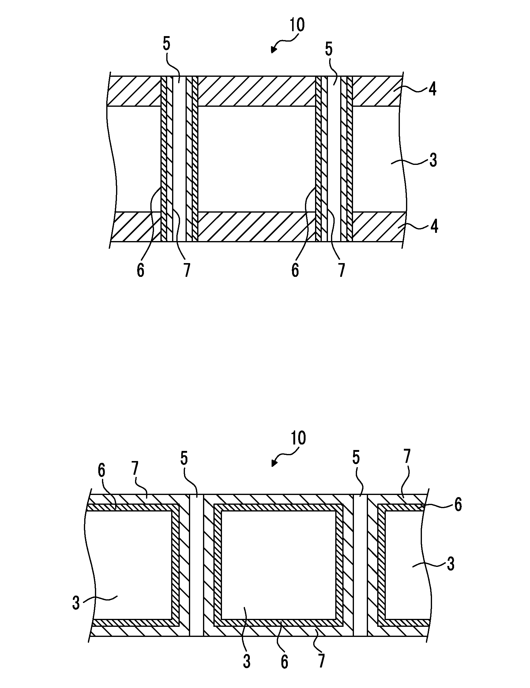
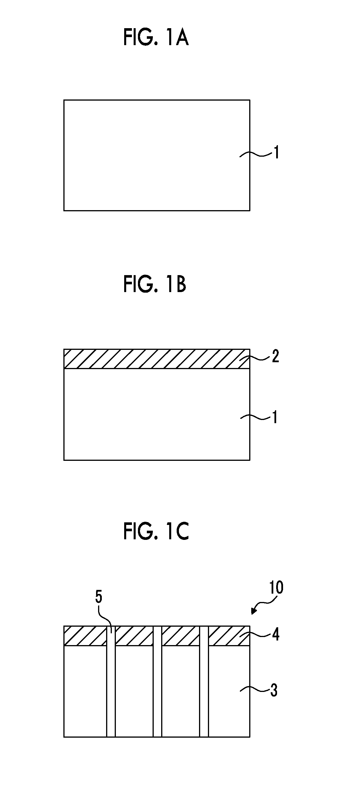

Image

  • Method for manufacturing aluminum plate, aluminum plate, collector for storage device, and storage device
  • Method for manufacturing aluminum plate, aluminum plate, collector for storage device, and storage device
  • Method for manufacturing aluminum plate, aluminum plate, collector for storage device, and storage device

Examples


example 1

Production of Aluminum Substrate for Collector

[0221]A treatment which will be described below was carried out on the surface of an aluminum substrate having a thickness of 5 m and a width of 200 mm (JIS H-4160, alloy number: 1N30-H, aluminum purity: 99.30%), thereby producing an aluminum substrate for a collector.

[0222](a1) Oxidized Film-Forming Treatment (Oxidized Film-Forming Step)

[0223]Direct-current voltage of 15 V was applied to the aluminum substrate for 16 seconds at a direct current density of 25 A / dm2 under a condition of 52° C. using a solution having an aluminum concentration of 5% or lower and the aluminum substrate as an anode at a sulfuric acid concentration of 170 g / L, thereby forming an oxidized film (the amount of the coating: 2.4 g / m2) on a single-side surface (single surface) of the aluminum substrate. After that, water washing was carried out by means of spraying.

[0224](b1) Electrolytic Dissolution Treatment (Through Hole-Forming Step)

[0225]Next, an electrolytic ...

examples 2 to 14

[0230]Aluminum plates were produced using the same method as in Example 1 except for the fact that the thicknesses (t) of the aluminum substrates and the quantities of electricity (Q) in the electrolytic dissolution treatment were changed to values shown in Table 2 below, and, in Example 5, an electrolytic roughening treatment described in (d1) below was carried out after the removal treatment of oxidized films described in (c1).

[0231](d1) Electrolytic Roughening Treatment

[0232]Next, an electrochemical roughening treatment was continuously carried out on the aluminum substrate that had been subjected to the removal treatment of oxidized films using 60 Hz alternating-current voltage. At this time, the electrolytic solution was an aqueous solution of 10 g / L of nitric acid (including 4.5 g / L of aluminum ions), and the temperature was 50° C. The alternating-current power source waveform was the waveform illustrated in FIG. 4, and the electrochemical roughening treatment was carried out ...

example 15

[0233]An aluminum plate was produced using the same method as in Example 1 except for the fact that a removal treatment of oxidized films described in (c2) below was carried out instead of the removal treatment of oxidized films described in (c1).

[0234](c2) Removal Treatment of Oxidized Films (Oxidized Film-Removing Step)

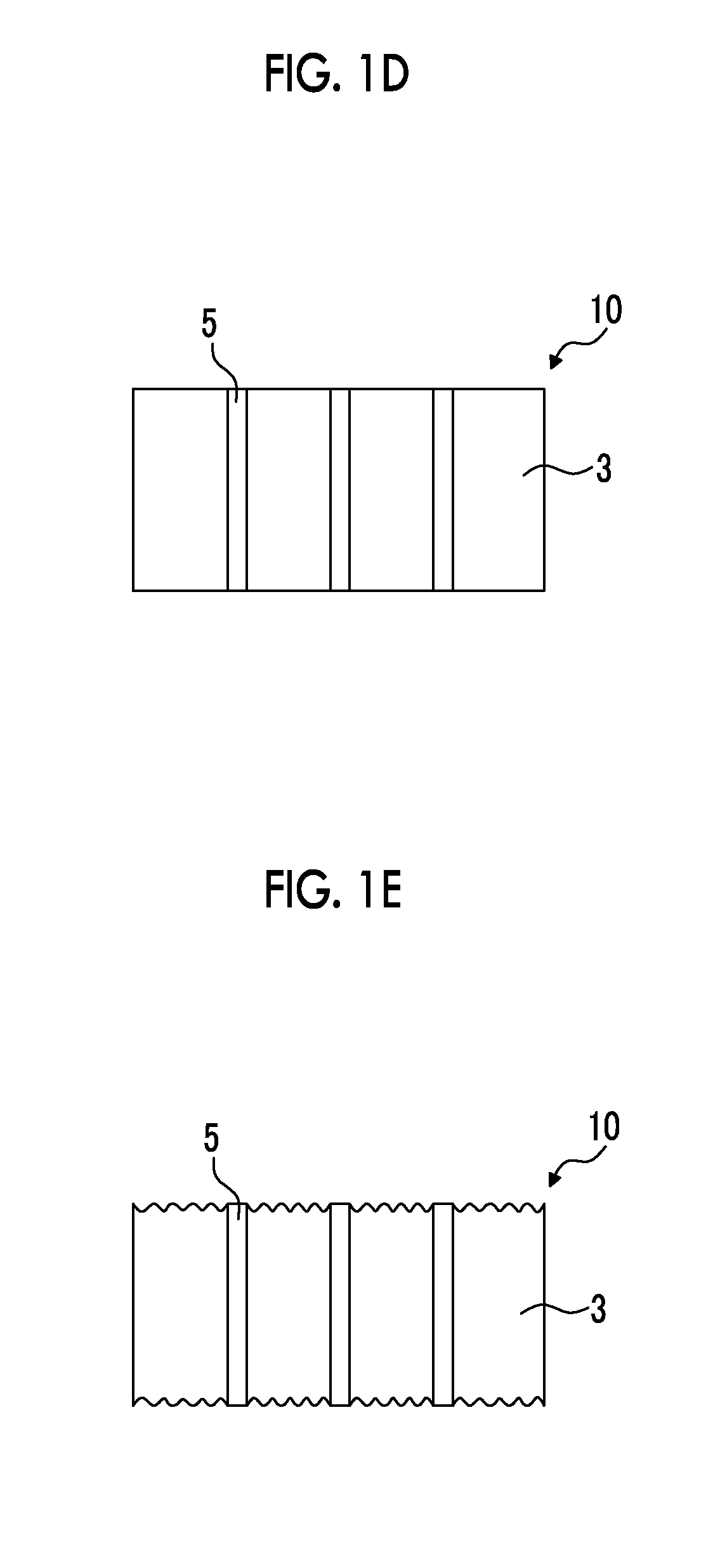
[0235]Next, the aluminum substrate that had been subjected to the electrolytic dissolution treatment was immersed in a sulfuric acid aqueous solution (sulfuric acid concentration: 300 g / L, liquid temperature: 60° C.) for 120 seconds, thereby dissolving and removing the oxidized film.

[0236]After that, the aluminum substrate was washed with water by means of spraying and was dried, thereby producing an aluminum plate having through holes. Meanwhile, in Table 2 below, the removal treatment of oxidized films under this condition is denoted as “acid”.


PUM

PropertyMeasurementUnit
Lengthaaaaaaaaaa
Lengthaaaaaaaaaa
Lengthaaaaaaaaaa

Abstract

An object of the present invention is to provide a method for manufacturing an aluminum plate which is simple, is high in productiveness, allows the use of arbitrary aluminum materials, and can be suitably used for collectors having excellent adhesiveness to active material layers, a collector for a storage device, and a storage device. The method for manufacturing an aluminum plate of the present invention is a method for manufacturing an aluminum plate having an aluminum substrate having a plurality of through holes in a thickness direction, including an oxidized film-forming step of forming an oxidized film by carrying out an oxidized film-forming treatment on a surface of the aluminum substrate having a thickness in a range of 5 μm to 1,000 μm and a through hole-forming step of forming through holes by carrying out an electrochemical dissolution treatment after the oxidized film-forming step.

Description

CROSS-REFERENCE TO RELATED APPLICATIONS[0001]This application is a Continuation of PCT International Application No. PCT / JP2015 / 052482 filed on Jan. 29, 2015, which claims priority under 35 U.S.C. §119(a) to Japanese Patent Application No. 2014-017244 filed on Jan. 31, 2014, Japanese Patent Application No. 2014-070042 filed on Mar. 28, 2014 and Japanese Patent Application No. 2014-202506 filed on Sep. 30, 2014. Each of the above application(s) is hereby expressly incorporated by reference, in its entirety, into the present application.BACKGROUND OF THE INVENTION[0002]1. Field of the Invention[0003]The present invention relates to a method for manufacturing an aluminum plate, an aluminum plate, a collector for a storage device, and a storage device.[0004]2. Description of the Related Art[0005]In recent years, in response to the development of portable devices such as personal computers and mobile phones, hybrid vehicles, electric vehicles, and the like, the demand for storage devices...

Claims


Application Information

Patent Timeline
IPC IPC(8): H01M10/0525C25D11/20C25D11/24H01G11/70H01M4/66H01M4/80H01G11/68H01G11/84C25F3/04H01M4/04
CPCH01M10/0525C25F3/04C25D11/20C25D11/24H01M4/0442H01M2004/021H01M4/661H01M4/80H01G11/68H01G11/84H01G11/70H01M4/044C23C18/1653C23C18/54C25D3/38C25D11/18H01M4/664H01M4/667Y02E60/10Y02T10/70Y02E60/13
Inventor MATSUURA, ATSUSHIKASUYA, YUICHIKAWAGUCHI, JUNJIHOTTA, HISASHIHOTTA, YOSHINORIKOMATSU, HIROSHISAWADA, HIROKAZU
Owner FUJIFILM CORP
Learn More