Multichannel receiver

a multi-channel receiver and receiver technology, applied in the field of communication equipment, can solve problems such as problems in the design of receivers, and achieve the effects of reducing phase noise and emi, reducing power consumption, and small siz

Inactive Publication Date: 2016-10-06
ALCATEL-LUCENT USA INC
View PDF4 Cites 30 Cited by
  • Summary
  • Abstract
  • Description
  • Claims
  • Application Information

AI Technical Summary

Benefits of technology

[0007]An embodiment of a disclosed multichannel receiver may use a single master clock to generate (i) the sampling-clock signal that sets the sampling rate of the receiver's ADC and (ii) multiple electrical local-oscillator signals that are used in various channels of the receiver's analog down-converter to translate to intermediate frequency the RF signals received on the receiver's array of antennas. The multichannel receiver may employ a plurality of interconnected frequency dividers configured to variously divide the master-clock frequency to generate the sampling-clock signal and the multiple local-oscillator signals in a manner that causes these signals to have different respective frequencies. The use of a single master clock may advantageously enable the multichannel receiver to have a smaller size, consume less power, and exhibit lower levels of phase noise and EMI than conventional receivers that rely on multiple PLLs to generate sampling-clock and local-oscillator signals.

Problems solved by technology

However, the use of wider bandwidths, multiple spectral bands, and / or spectrum sharing introduces new challenges to the receiver design.

Method used


Image

  • Multichannel receiver
  • Multichannel receiver
  • Multichannel receiver

Examples


Embodiment Construction

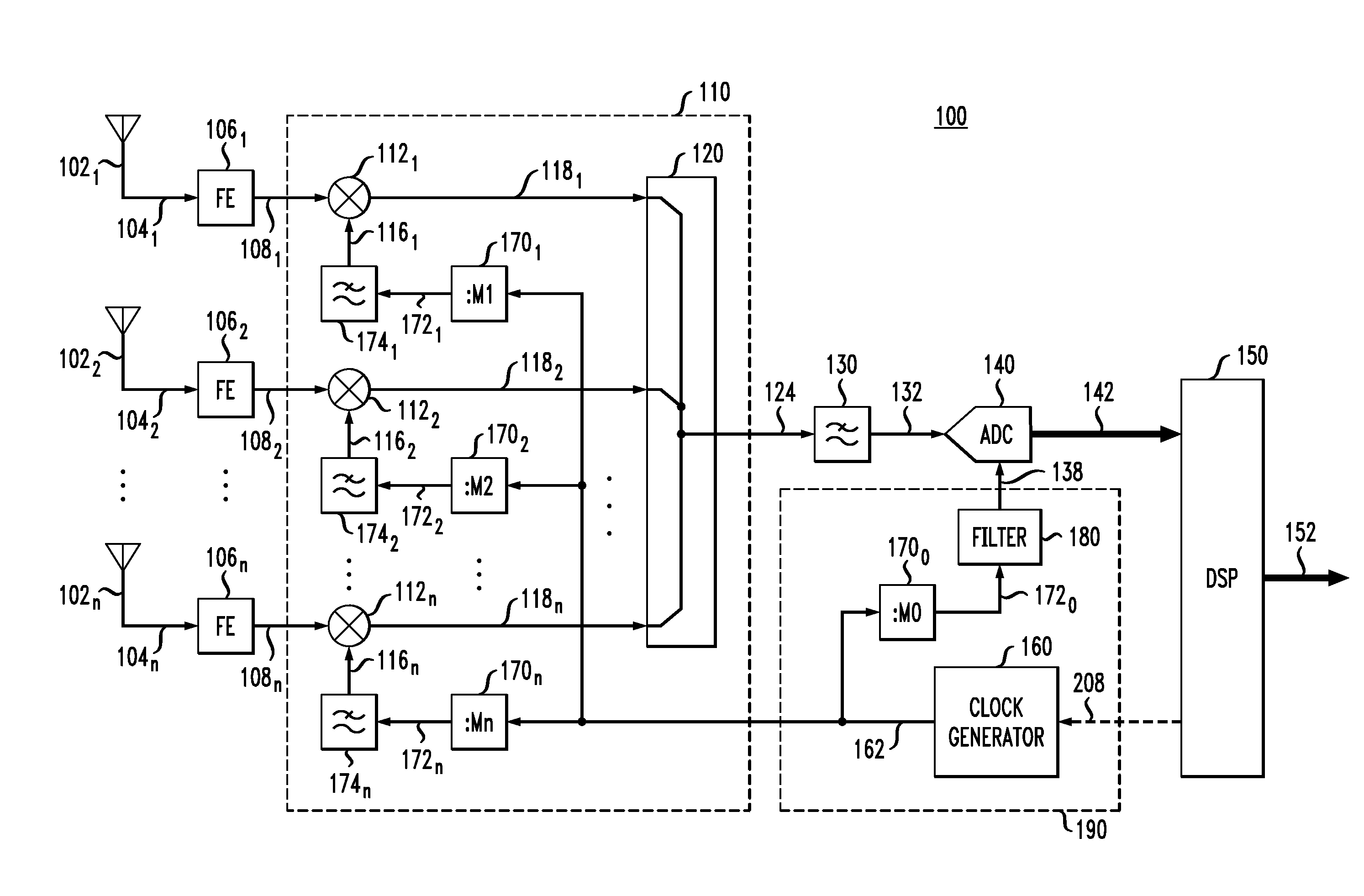
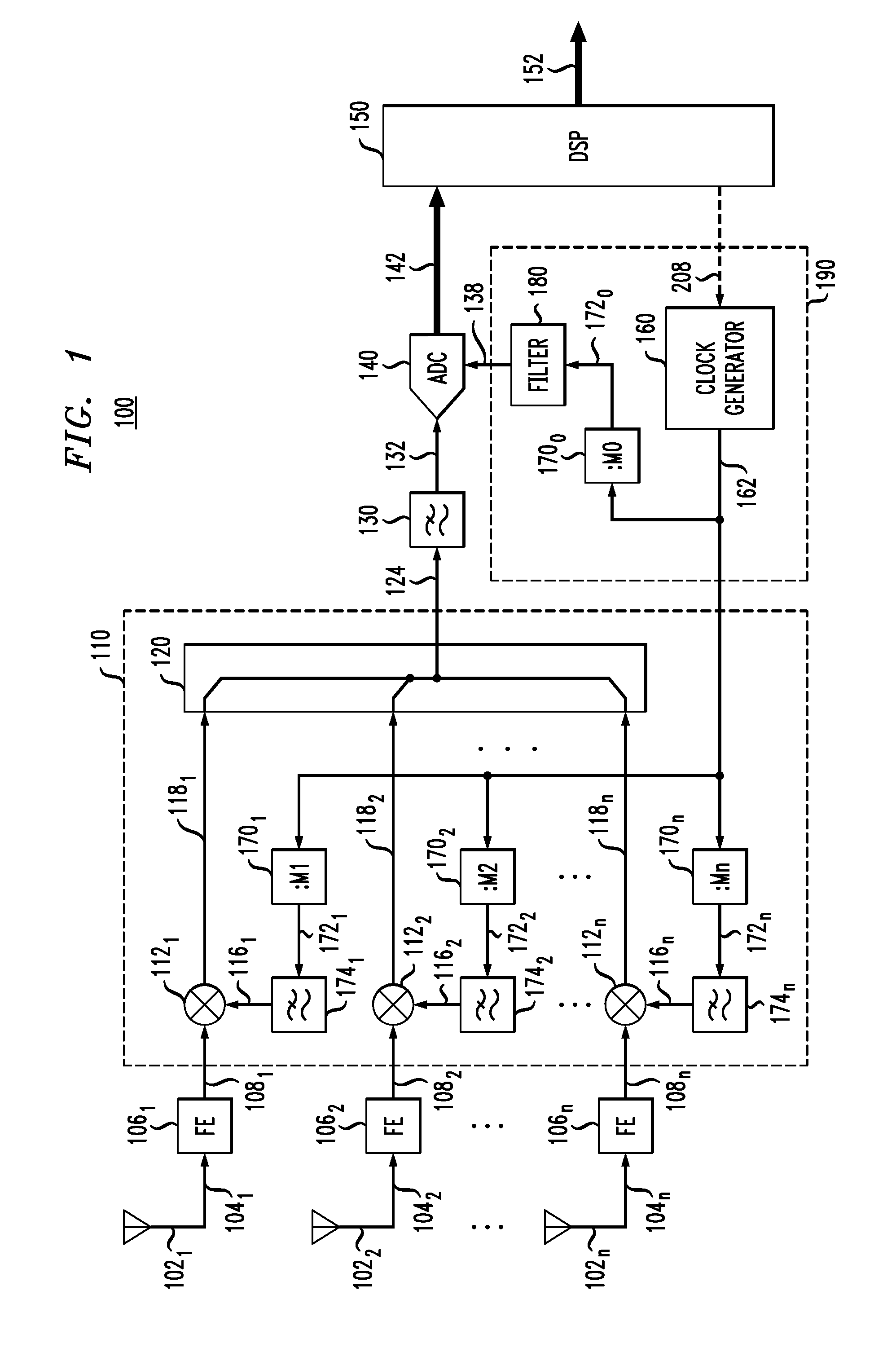
[0006]Whereas multichannel-receiver architectures often need local oscillator (LO) signals in multiple spectral bands, a phase-lock loop (PLL) for providing a LO signal is a relatively complex circuit. Such a circuit can take up a relatively large chip area and / or consume considerable power. In addition, a PLL may result in an increased level of electromagnetic interference (EMI), ground bouncing, frequency pulling, and other deleterious effects that tend to degrade the overall receiver performance.

[0007]An embodiment of a disclosed multichannel receiver may use a single master clock to generate (i) the sampling-clock signal that sets the sampling rate of the receiver's ADC and (ii) multiple electrical local-oscillator signals that are used in various channels of the receiver's analog down-converter to translate to intermediate frequency the RF signals received on the receiver's array of antennas. The multichannel receiver may employ a plurality of interconnected frequency dividers ...


PUM


Abstract

An embodiment of the disclosed multichannel receiver may use a single master clock to generate (i) the sampling-clock signal that sets the sampling rate of the receiver's ADC and (ii) multiple electrical local-oscillator signals that are used in various channels of the receiver's analog down-converter to translate to intermediate frequency the RF signals received on the receiver's array of antennas. The multichannel receiver may employ a plurality of interconnected frequency dividers configured to variously divide the master-clock frequency to generate the sampling-clock signal and the multiple local-oscillator signals in a manner that causes these signals to have different respective frequencies.

Description

BACKGROUND[0001]1. Field[0002]The present disclosure relates to communication equipment and, more specifically but not exclusively, to radio-frequency (RF) receivers.[0003]2. Description of the Related Art[0004]This section introduces aspects that may help facilitate a better understanding of the disclosure. Accordingly, the statements of this section are to be read in this light and are not to be understood as admissions about what is in the prior art or what is not in the prior art.[0005]Recent development of very high-speed, high-resolution, and high-dynamic-range linear analog-to-digital converters (ADCs) enables implementation of certain RF-receiver functions using a digital signal processor (DSP) instead of the analog RF hardware conventionally used for these purposes in the previous generation of RF receivers. However, the use of wider bandwidths, multiple spectral bands, and / or spectrum sharing introduces new challenges to the receiver design.SUMMARY OF SOME SPECIFIC EMBODIM...

Claims


Application Information

Patent Timeline
Patent Type & Authority Applications(United States)
IPC IPC(8): H04L27/22H03M1/12
CPCH03M1/124H04L27/22H04B1/10H04B1/06H04B1/1036H04L7/0008
Inventor KURCHUK, BORIS A.HONCHARENKO, WALTER
Owner ALCATEL-LUCENT USA INC
Why Eureka
Try Eureka