3D infiltration method

Active Publication Date: 2016-10-20
VOXELJET AG
View PDF3 Cites 55 Cited by
  • Summary
  • Abstract
  • Description
  • Claims
  • Application Information

AI Technical Summary

Benefits of technology

[0018]In one aspect, the invention relates to a method for producing strengthened 3D components, the component being able to be produced using known 3D printing methods, and the method being

Problems solved by technology

Components that are produced using the methods described above, however, show the disadvantage that they have a porous structure and do not form solid, closed bodies.
The porosity is caused by the building process and is unavoidable, for example, in the area of cement-bound materials.
The porosity not only has disadvantages with regard to component stability and strength but it also involves numerous disadvantages in the long-term use of components of this type.
In particular, when using such components outdoors, a long-term durability is not ensured, and material fatigue or damage may occur due to various influences.
However, the use of components produced with 3D printing methods is problematic in many areas, since problems can be expected in long-term installation and occur to a proven degree, due to the porosity of the components.
First of all, frost shattering may occur in the components produced with 3D printing methods and thus damage or destroy the components.
Penetrating water generates high compressive forces when it freezes during the winter and breaks apart the 3D cement c

Method used


Image

  • 3D infiltration method
  • 3D infiltration method
  • 3D infiltration method

Examples


example

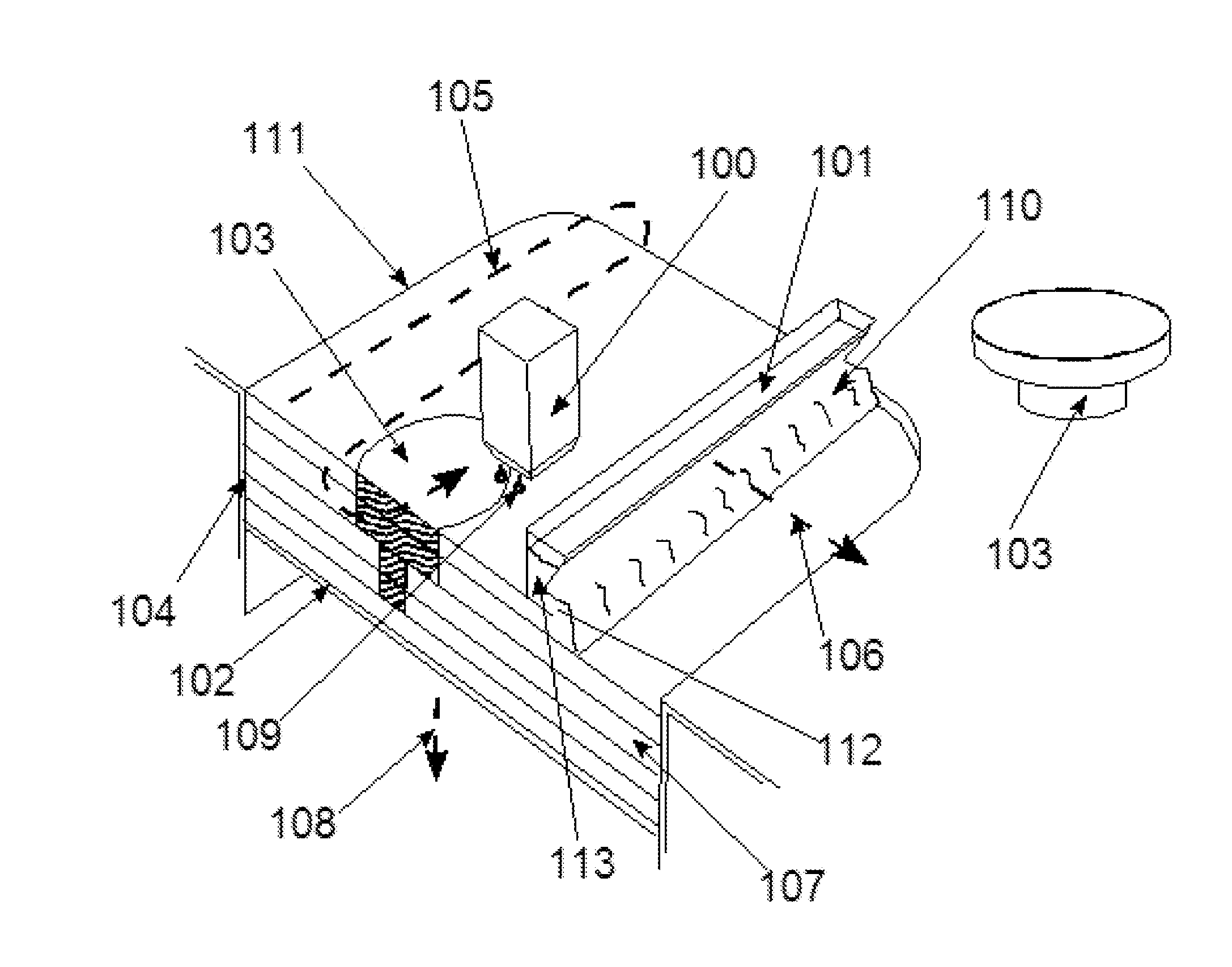
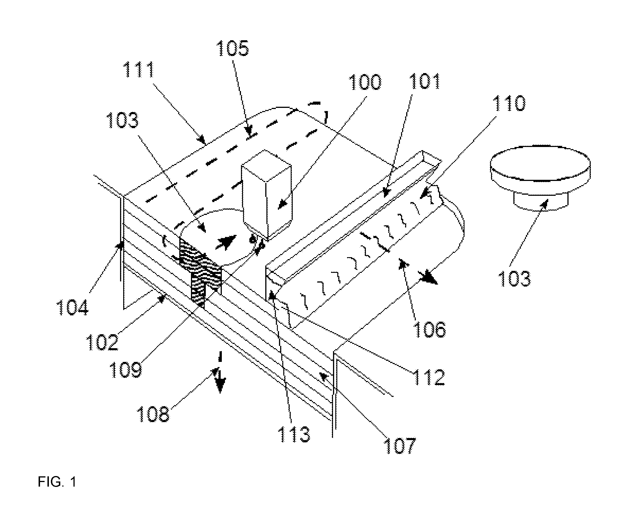
[0074]Producing a molded part using the method according to the invention

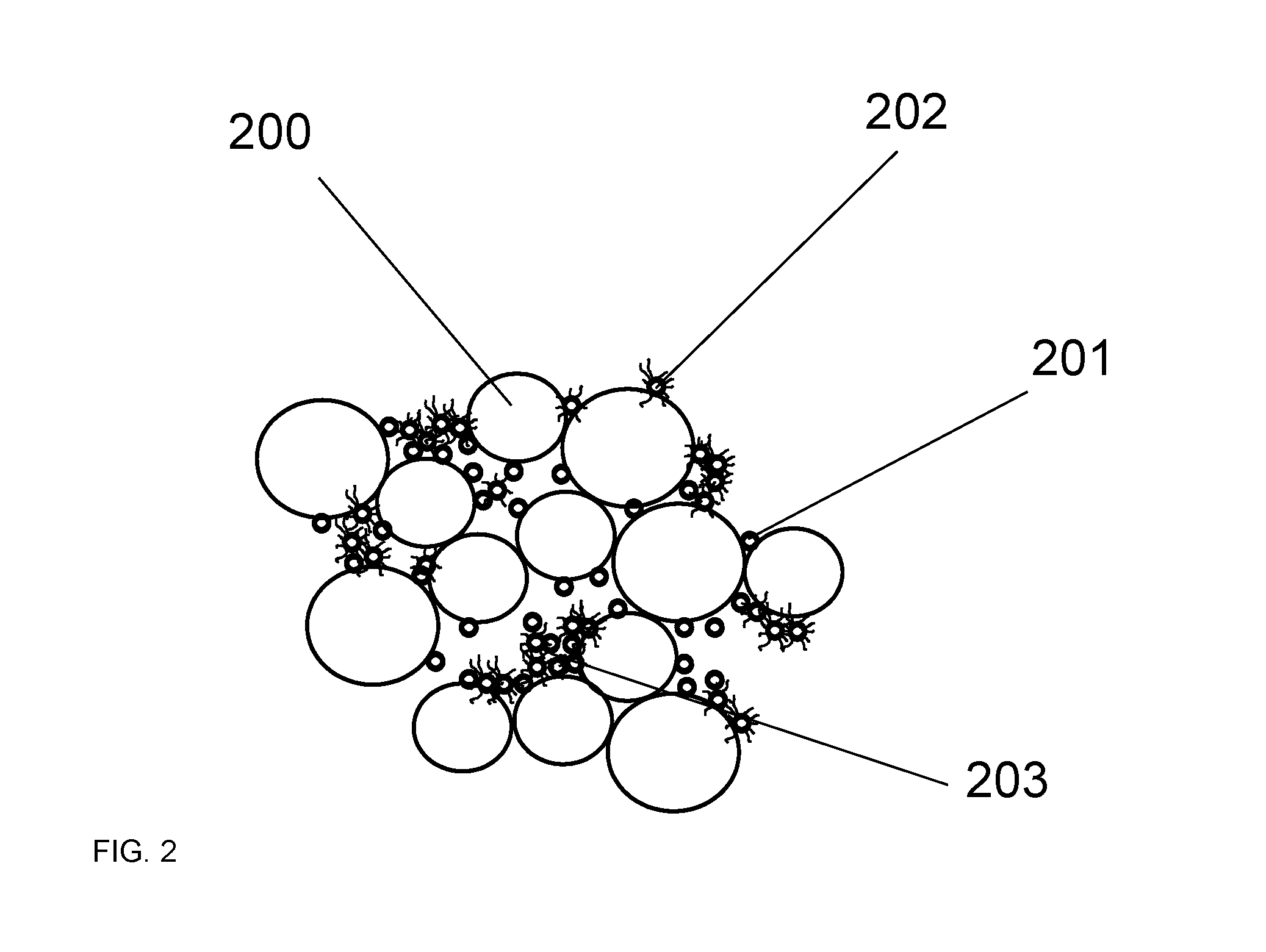
[0075]In the first step, a particulate material is applied in a thin layer to a building platform. In this preferred specific embodiment, the particulate material comprises silica sand (200) having an average grain size of 140 μm. Before being applied, this sand is dried until the residual moisture is less than 0.3 wt. %. A cement grain mixture (201), which is adapted to the pore space, is added to this sand mixture. The reactivity of this cement may be adapted. The layer thickness in this process is 0.25 mm.

[0076]Pyrogenic silicic acid in a proportion of 0.5 wt. % is also added to modify the flowability of the particle mixture. The cement may be, for example, a CA270-type calcium aluminate cement from Almatis or an Alphabond 300 from Almatis.

[0077]The binding fluid contains a silicate in order to adjust the printability. The latter is present in an aqueous solution. In addition Surfynol 440 surfactants are use...


PUM

PropertyMeasurementUnit
Timeaaaaaaaaaa
Solubility (mass)aaaaaaaaaa
Heataaaaaaaaaa

Abstract

The invention relates to a method for producing three-dimensional molded parts in two method steps and infiltrating the molded part, as well as a material system.

Description

[0001]The invention relates to a method for producing solidified three-dimensional components as well as a material system suitable for a 3D printing method.[0002]A method for producing three-dimensional objects from computer data is described in the European patent specification EP 0 431 924 B1. In this method, a particulate material is applied in a thin layer to a platform, and a binder material is selectively printed onto the particulate material, using a print head. The particle area onto which the binder is printed sticks together and solidifies under the influence of the binder and, if necessary, an additional hardener. The platform is then lowered by a distance of one layer thickness into a build cylinder and provided with a new layer of particulate material, which is also printed as described above. These steps are repeated until a certain, desired height of the object is reached. A three-dimensional object (component, molded body, 3D molded part) is thereby produced from th...

Claims


Application Information

Patent Timeline
IPC IPC(8): B28B7/46B29C67/00B33Y70/00B33Y80/00B28B1/00C04B41/45B28B7/44B28B11/04B33Y40/00B22F3/10B23K31/02B33Y10/00B28B11/24
CPCB28B7/465B29K2105/251B29C67/0081B33Y70/00B33Y80/00B28B1/001B28B11/24B28B7/44B28B11/045B28B11/048B28B11/04B33Y40/00B22F3/10B23K31/02C04B41/4545B33Y10/00C04B37/026C04B2237/12C04B2237/121C04B2237/124C04B2237/125C04B2237/366C04B2237/402C04B2237/407B29C64/165B29C64/188B33Y40/20B33Y70/10
Inventor GUNTHER, DANIEL
Owner VOXELJET AG
Why Eureka
Try Eureka