
Device for applying heat radiation to a surface

a surface heat radiation and heat dissipation technology, applied in the field of devices for achieving the effect of increasing the heat dissipating surface area and facilitating the reach of hard-to-reach areas

Active Publication Date: 2016-10-27
SPEEDHEATER SYST
View PDF12 Cites 5 Cited by
  • Summary
  • Abstract
  • Description
  • Claims
  • Application Information

AI Technical Summary

Benefits of technology

This patent describes a device with a heat dissipating member that helps to prevent injury from high temperatures. The device uses a curved heat dissipating member with a larger surface area, which improves heat insulation without increasing the thickness of the member. The device is made of a plastic with good heat insulating properties. The head assembly of the device can be pivoted, making it easier to reach hard-to-reach areas. The technical effects of this device are improved heat dissipation, prevention of burn injuries, and better ergonomics for holding and using the device.

Problems solved by technology

For example, the paint removal can be carried out by means of scraping or grinding, which either implies a great effort of costly manpower or diffusion of ecologically harmful dust and disturbing noise.
However, the open flame of a blow torch constitutes a fire hazard and it is difficult to gain real efficiency and an equally distributed heating to the right temperature with a hot air gun.
These methods involve various disadvantages, such as negative environmental effects, drying of the wood (resulting in cracks), not to mention the fact that many hydrocarbon based solutions are very toxic.

Method used


Image

  • Device for applying heat radiation to a surface
  • Device for applying heat radiation to a surface
  • Device for applying heat radiation to a surface

Examples


Embodiment Construction

[0045]The invention will now be described with reference to the accompanying drawings, wherein like characters denote like or corresponding parts.

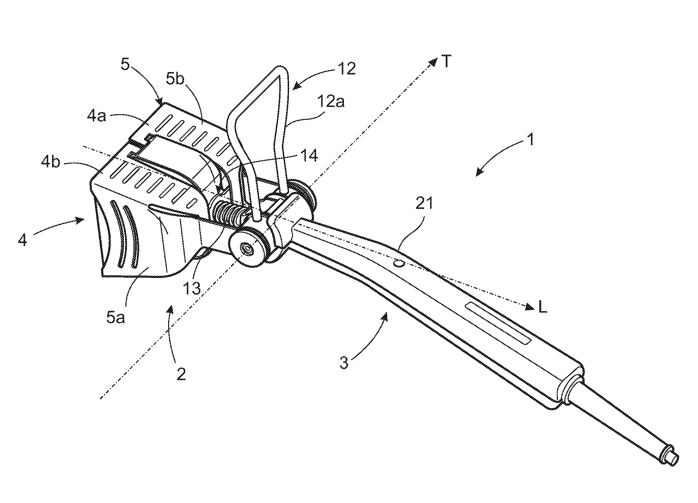
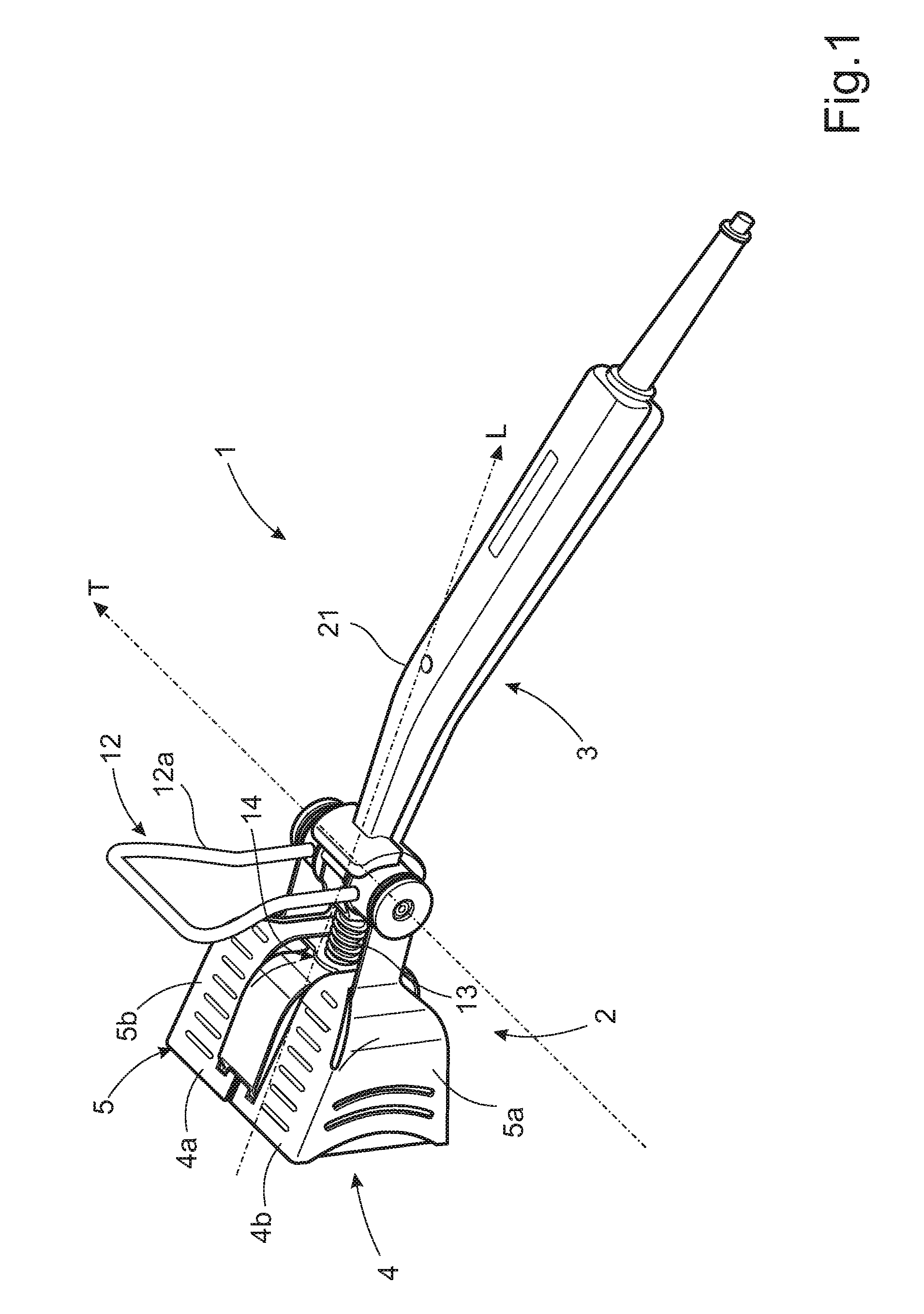
[0046]FIG. 1 shows a perspective view of a first embodiment of a device 1 for applying heat radiation to a surface. The device 1 comprises a head assembly 2 and a handle assembly 3 separated by a clearance. The device has a longitudinal axis L and a transverse axis T.

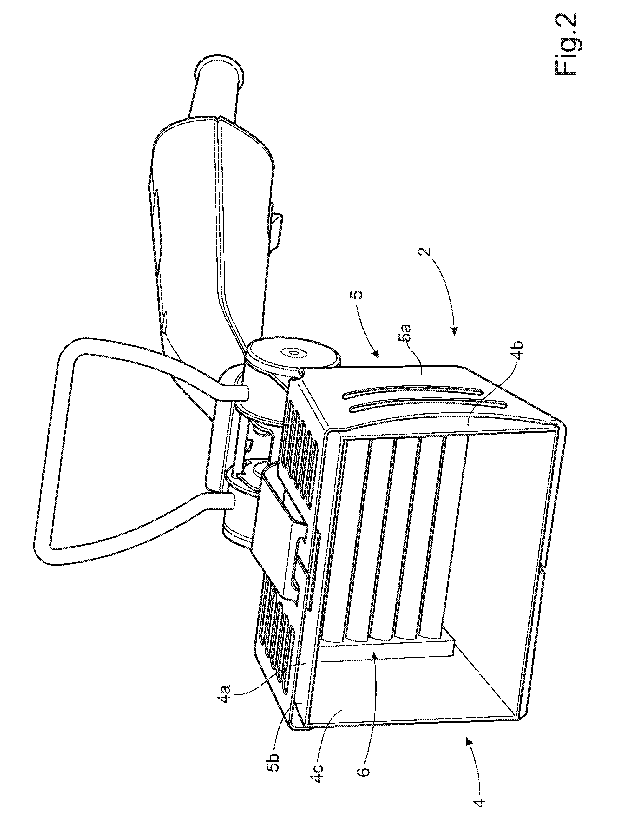
[0047]Now referring to FIGS. 1 and 2, the head assembly 2 comprises a reflector unit 4 mounted in a protective casing 5. A heat radiation element 6 comprising a plurality of electric resistance wires arranged in tubes made of quartz crystal is mounted within the reflector unit 4. The reflector unit 4 comprises a U-shaped central part 4a and two side walls 4b, 4c connected to the central part so as to define a space enclosed on five sides, which space houses the heat radiation element 6. The central part 4a and the side walls 4b, 4c also define an aperture intended to face the ...


PUM


Abstract

A device (1) for applying heat radiation to a surface, for softening and / or removing one or more coatings, includes a head assembly (2) and a handle assembly (3) connected to the head assembly. The head assembly includes at least one heat radiation element (6) arranged in a reflector unit (4), which has an aperture intended to be directed towards the surface to be radiated. The head assembly and the handle assembly are separated by a clearance and at least one heat dissipating member that spans the clearance connects a first attachment area (14) of the head assembly and a second attachment area (16) of the handle assembly. At least a portion of the heat dissipating member has a curvature such that the length of the heat dissipating member exceeds the distance between the first and second attachment areas.

Description

SUBJECT OF THE INVENTION[0001]The present invention relates to a device for applying heat radiation to a surface, for softening and / or removing one or more coatings on said surface. The device comprises a head assembly and a handle assembly connected to the head assembly. The head assembly comprises at least one heat radiation element arranged in a reflector unit, which reflector unit has an aperture intended to be directed towards the surface to be radiated.BACKGROUND OF THE INVENTION[0002]It is sometimes necessary to remove one or more layers of coating from a surface. For example, during renovation of old houses, it is normally required to remove several coats of paint from the walls of said houses. Various methods are available for executing this work. For example, the paint removal can be carried out by means of scraping or grinding, which either implies a great effort of costly manpower or diffusion of ecologically harmful dust and disturbing noise. Alternatively, the paint ca...

Claims


Application Information

Patent Timeline
IPC IPC(8): B44D3/16H05B3/00
CPCH05B3/0038B44D3/168B25G3/38B08B1/165B44D3/166B25G3/20B25G3/00
Inventor ERICSSON, BIRGER
Owner SPEEDHEATER SYST
Learn More