Magnetic Field Measuring Apparatus
a technology of light source apparatus and measuring apparatus, which is applied in the direction of instruments, semiconductor lasers, non-linear optics, etc., can solve the problems of not considering the stable operation of light intensity, the influence of light intensity fluctuation caused in the glass cell cannot be prevented, and it is not possible to realize stable and highly sensitive magnetic field detection. , to achieve the effect of stabilizing the signals in the magnetic field measuremen
- Summary
- Abstract
- Description
- Claims
- Application Information
AI Technical Summary
Benefits of technology
Problems solved by technology
Method used
Image
Examples
first embodiment
aratus
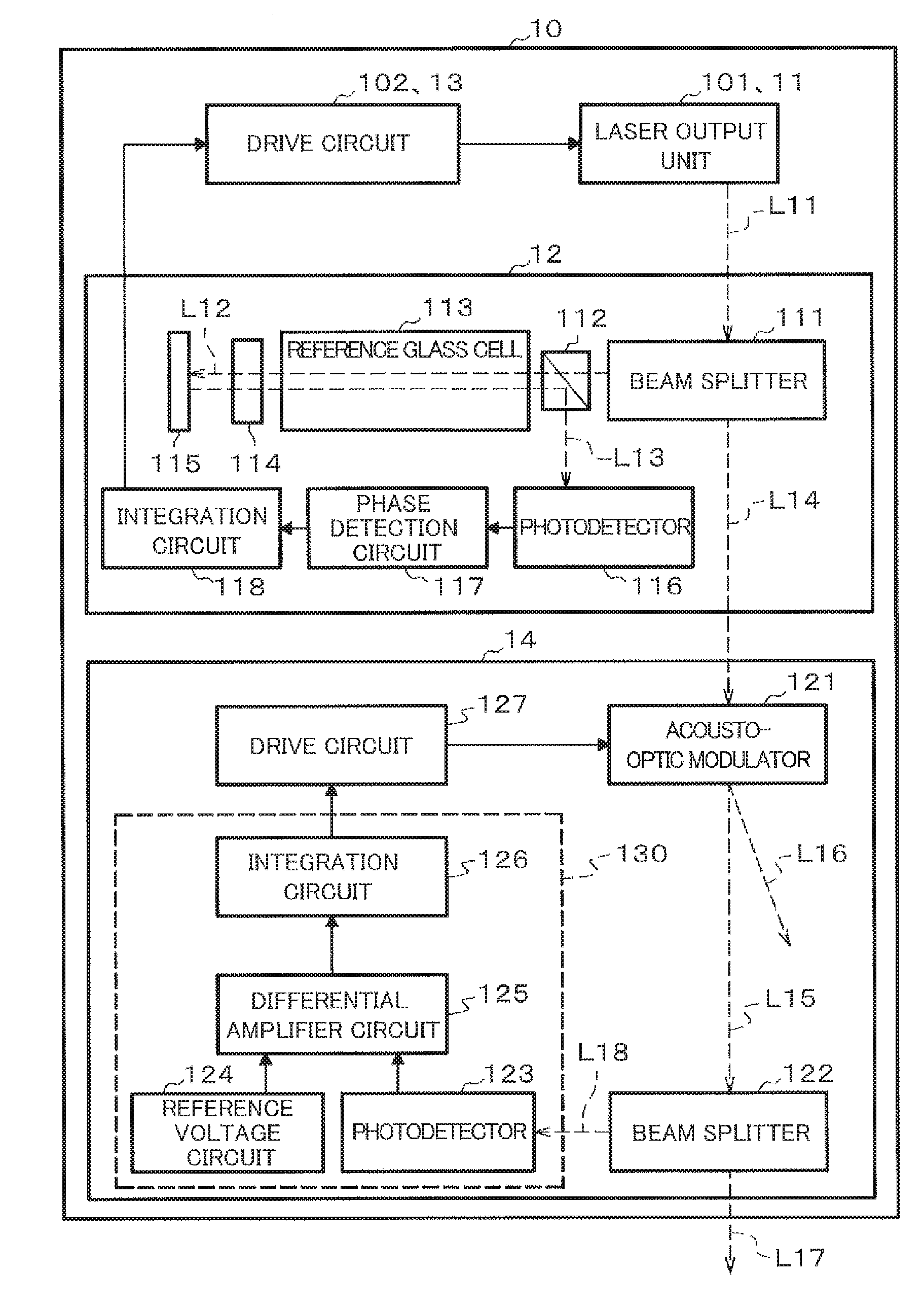
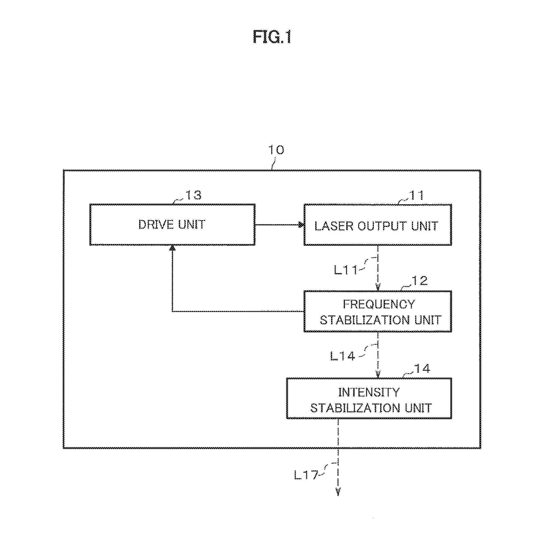
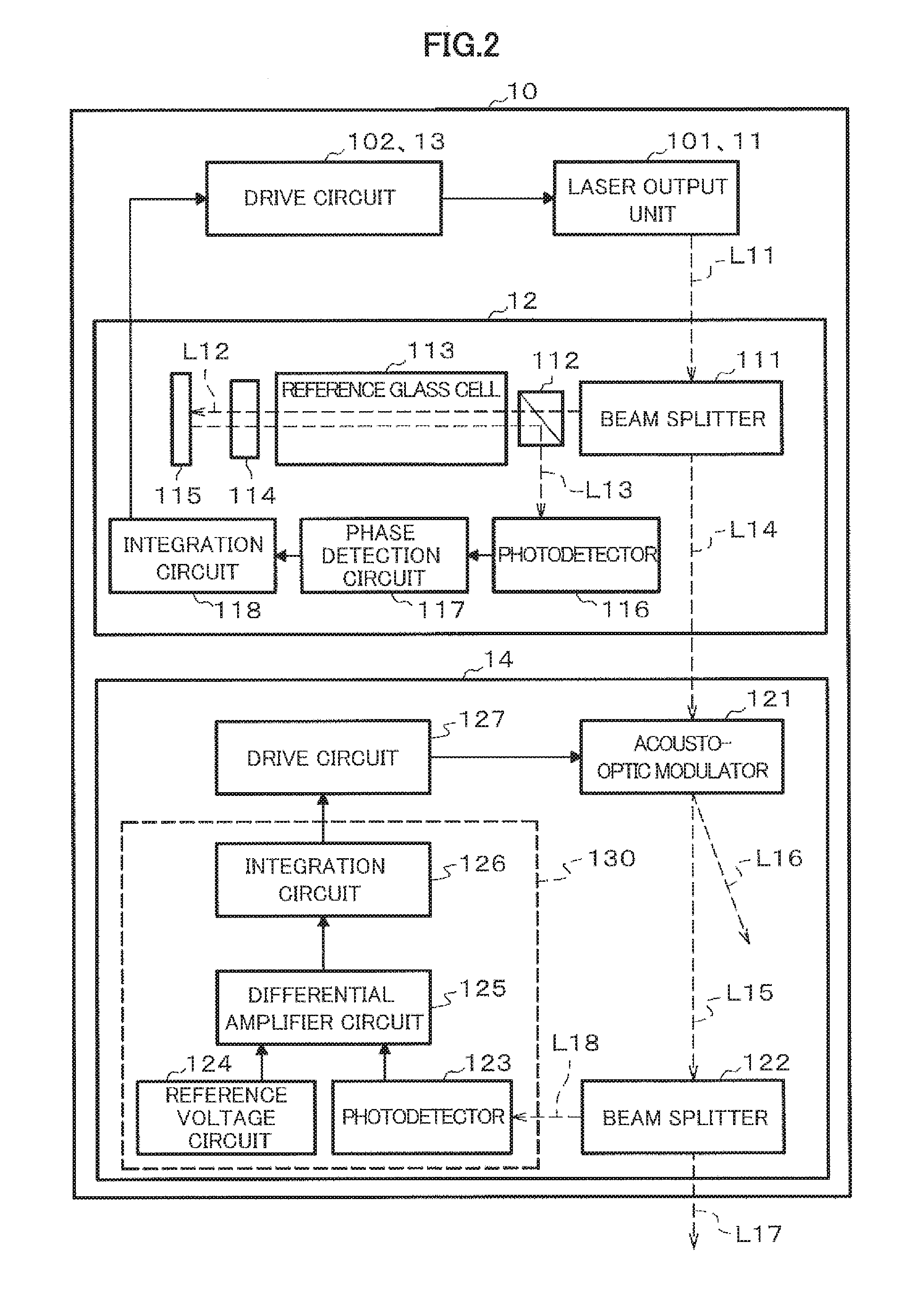
[0038]FIG. 1 is a diagram showing a schematic configuration example of a light source apparatus according to a first embodiment. A light source apparatus 10 includes a laser output unit (light generating unit) 11, a frequency stabilization unit 12, an intensity stabilization unit 14 and a drive unit 13. The laser output unit 11 generates and outputs a laser beam L11 by being applied with voltage. The frequency stabilization unit 12 stabilizes frequency of the laser beam L11 outputted from the laser output unit 11 by controlling the drive unit 13. The intensity stabilization unit 14 stabilizes light intensity of a laser beam L14 outputted from the frequency stabilization unit 12, and outputs a laser beam L17 having a stabilized light intensity. Note that, the intensity stabilization unit 14 is preferably provided as a separate unit in a subsequent stage of the frequency stabilization unit 12. In this way, it is possible to stabilize the light intensity of the laser beam L14 hav...
second embodiment
[0061]The magnetic field measuring apparatus according to a second embodiment of the present invention will be described with reference to FIGS. 3 to 5. A magnetic field measuring apparatus 20 according to the second embodiment is for detecting a magnetic field applied to a sensor unit 25 by using light-RF double resonance generated in an RF magnetic field. FIG. 3 is a diagram showing a configuration example of the magnetic field measuring apparatus according to the second embodiment. The magnetic field measuring apparatus 20 includes a light source unit 21, a light splitter 22, the sensor unit 25, a static magnetic field generator 26, an RF magnetic field generator 27, a signal control processor 24 and a magnetic field analyzer 50. The light source unit 21 is for outputting the light, and it is desirable to use the light source apparatus 10 of the first embodiment, however, it may not be used. The light splitter 2 splits a laser beam L21 outputted from the light source unit 21 into...
third embodiment
[0081]A magnetic field measuring apparatus according to a third embodiment will be described with reference to FIGS. 6 to 8. The magnetic field measuring apparatus according to the third embodiment is for detecting the magnetic field of the measurement object, which is applied to a sensor unit 35, by using light-RF double resonance generated in the RF magnetic field in the same manner as the second embodiment. FIG. 6 is a diagram showing a configuration example of the magnetic field measuring apparatus according to the third embodiment. The magnetic field measuring apparatus 30 includes a light source unit 31, a light splitter 32, the sensor unit 35, a static magnetic field generator 36, an RF magnetic field generator 37, a signal control processor 34, the magnetic field analyzer 50 and a light intensity control unit 39. The light source unit 31 is for outputting the light, and it is desirable to use the light source apparatus 10 of the first embodiment, however, it may not be used....
PUM
 Abstract
Description
Claims
Application Information
 - R&D
- Intellectual Property
- Life Sciences
- Materials
- Tech Scout
- Unparalleled Data Quality
- Higher Quality Content
- 60% Fewer Hallucinations
Browse by: Latest US Patents, China's latest patents, Technical Efficacy Thesaurus, Application Domain, Technology Topic, Popular Technical Reports.
© 2025 PatSnap. All rights reserved.Legal|Privacy policy|Modern Slavery Act Transparency Statement|Sitemap|About US| Contact US: help@patsnap.com


