Method for controlling an operating point change of a fuel cell stack and a fuel cell system

a technology of fuel cell stack and operating point change, which is applied in the direction of fuel cells, transportation hydrogen technology, climate sustainability, etc., can solve the problems of corresponding power input or energy input, and achieve the effect of reducing the degradation of catalytic materials

Active Publication Date: 2016-10-27
VOLKSWAGEN AG +1
View PDF3 Cites 3 Cited by
  • Summary
  • Abstract
  • Description
  • Claims
  • Application Information

AI Technical Summary

Benefits of technology

[0010]It is an object of the present invention to provide a method for controlling an operating point change of a fuel cell stack, which at least partially eliminates the problems of the prior art. In particular, a degradation of the catalytic material is to be reduced or even prevented over a preferably large operating range of the fuel cell system.
[0013]Thus, according to the present invention, the dynamic operation of a fuel cell stack, in particular, a positive load requirement of the latter, is used in order to pass through temporary low stack voltages and, therefore, low single cell voltages. Low stack voltages or single cell voltages result namely in a re-deposition and recrystallization of dissolved catalytic materials of the catalytic electrodes, in particular, the cathode. In addition, low voltages cause oxides of the formed catalytic material to be reduced while regaining the original metallic form. The utilization of an operating point change for effectuating such a regeneration of the catalytic material results in a regeneration of the catalytic material being frequently carried out in the entire operating range, for example, of a fuel cell vehicle. The utilization of a positive load requirement for the targeted induction of low cell voltages also has the advantage that the surplus amount of current generated by the starting of a low voltage may be collected directly by the main electrical consumers or auxiliary consumers or an electric energy store. When utilizing stationary operating points for regenerating the catalytic material as described in the prior art, the generated amount of current must always be collected by the battery or by the on-board electrical system. Generally, however, both lack corresponding power inputs or energy inputs, or the battery must have a correspondingly low state of charge in order to be able to collect the current. Thus, the utilization according to the present invention of dynamic operating states for the active induction of low cell voltages for regenerating the catalyst electrodes facilitates a fuel cell system dynamic as required on the one hand, and an effective catalyst regeneration on the other hand, and thus, a higher fuel cell efficiency with simultaneous load point changes causing little damage.
[0016]The electric power is preferably controlled during the operating point change in accordance with the predetermined current-voltage profile by altering the mass flows of the anode operating medium and / or of the cathode operating medium of the fuel cell stack. Targeted interventions in the mass flows makes it possible to abandon the current-voltage characteristic curve (see FIG. 3) and to reach practically any operating point in the current-voltage characteristic map in a short period of time. This allows for the specific representation of the desired temporary voltage minimum. In addition, the control takes place preferably via the variation of the current drain from the fuel cell, i.e., current-controlled.
[0018]In an alternative, second strategy of the present invention, it is provided that the generated electric power is controlled in accordance with a current-voltage profile in such a way that the voltage initially steadily drops to a current intensity corresponding to the target power, and the voltage subsequently rapidly or suddenly increases at an essentially constant current intensity until it reaches a voltage corresponding to the target power. The voltage is preferably ramped down by reducing the mass flows of the reactants of the fuel cell, in particular, of the cathode operating medium. This results in a depletion of the oxidant supplied at the cathode, which is mostly oxygen. Once the target current intensity is reached, the voltage may be suddenly raised to the target operating point by a sudden increase in the mass flow of the cathode operating medium.
[0019]According to a third alternative strategy, the generated electric power is controlled in accordance with a current-voltage profile in such a way that initially the voltage is suddenly ramped down to the local voltage minimum and subsequently suddenly ramped up again, and the current intensity then increases until it reaches a current intensity corresponding to the target power. The voltage is preferably initially lowered to 0 volts, thus, the fuel cell stack is briefly switched off then quickly restarted. This is achieved preferably by a rapid shut-off of the cathode operating medium. The advantage of this strategy is the achievement of a particularly low single cell voltage and, therefore, a particularly good regeneration effect of the catalytic electrode material. This strategy may also result in an increased transfer of the anode operating medium, the fuel, to the cathode side. This boosts the reduction of cationic platinum by the fuel, for example, hydrogen.

Problems solved by technology

Generally, however, both lack corresponding power inputs or energy inputs, or the battery must have a correspondingly low state of charge in order to be able to collect the current.

Method used


Image

  • Method for controlling an operating point change of a fuel cell stack and a fuel cell system
  • Method for controlling an operating point change of a fuel cell stack and a fuel cell system
  • Method for controlling an operating point change of a fuel cell stack and a fuel cell system

Examples


Embodiment Construction

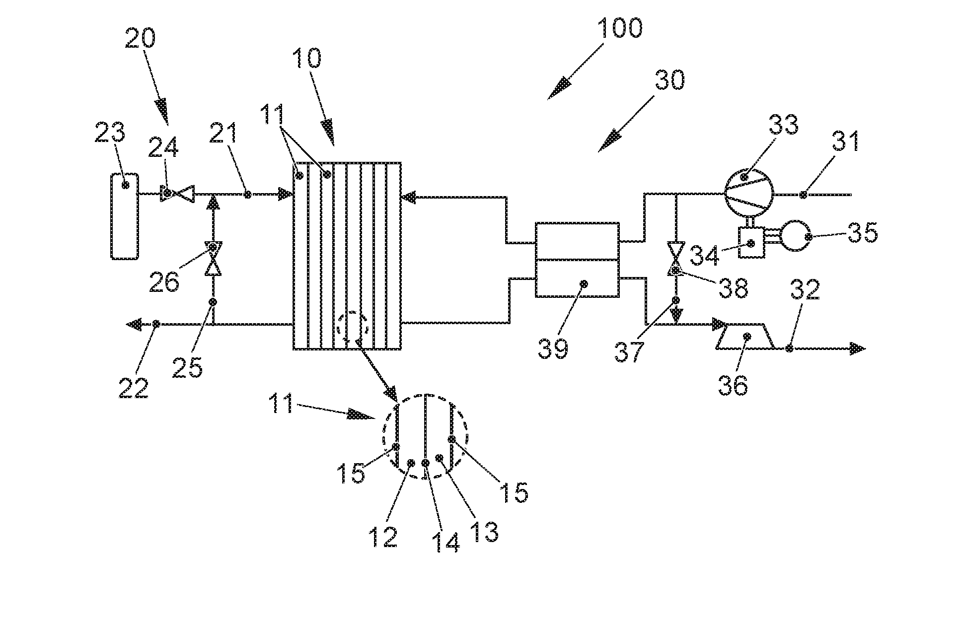
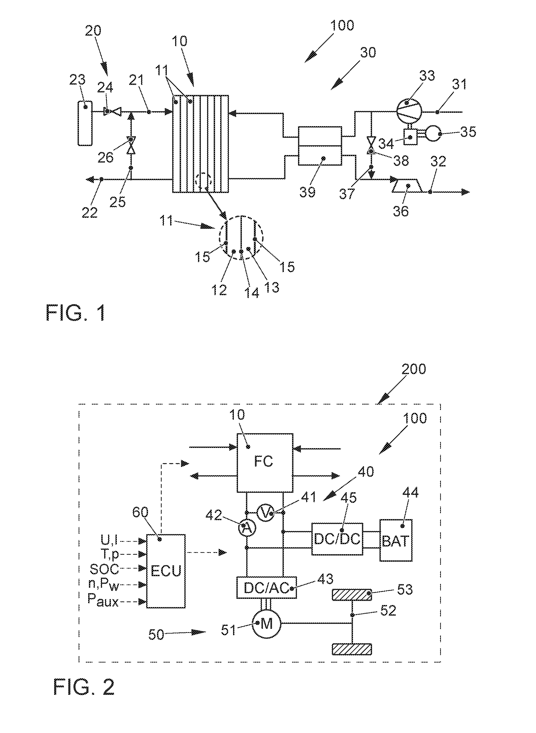
[0028]FIG. 1 shows a fuel cell system, indicated as a whole by reference numeral 100, according to a preferred embodiment of the present invention. Fuel cell system 100 is part of a vehicle not further depicted, in particular an electric vehicle, which includes an electric traction motor supplied with electric energy by fuel cell system 100.

[0029]Fuel cell system 100 includes a fuel cell stack 10 as the core component, which is composed of a plurality of single cells 11 assembled in a stack. Each single cell 11 includes an anode chamber 12 and a cathode chamber 13 separated from one another by an ion-conductive polymer electrode membrane 14 (see detailed view). Anode chamber and cathode chamber 12, 13 each include a catalytic electrode, the anode and the cathode, which catalyzes the respective partial reaction of the fuel cell conversion. The anode electrode and cathode electrode include a catalytic material, for example, platinum, which is supported on an electrically conductive ca...


PUM

PropertyMeasurementUnit
voltageaaaaaaaaaa
voltageaaaaaaaaaa
voltageaaaaaaaaaa

Abstract

A method for controlling an operating point change of a fuel cell stack (10) operated with an anode operating medium and with a cathode operating medium, in which the fuel cell stack (10) is controlled in such a way that, starting from an initial electric power (L1), the fuel cell stack generates a target power (L2) requested by an electrical consumer (51), which is greater than the initial power (L1) is provided. It is provided that the electric power generated by the fuel cell stack (10) is controlled in accordance with a predetermined current-voltage profile (S1, S2, S3), so that a voltage present at the fuel cell stack (10), starting from an initial voltage (U1) corresponding to the initial power (L1), passes through a local voltage minimum (Umin) and then increases to an end voltage corresponding to the target power (L2).

Description

[0001]This claims the benefit of German Patent Application DE102015207600.8, filed Apr. 24, 2015 and hereby incorporated by reference herein.[0002]The present invention relates to a method for controlling an operating point change of a fuel cell stack operated with an anode operating medium and a cathode operating medium, in which the fuel cell stack is controlled in such a way that, starting from an initial electric power, the stack generates a requested target power which is greater than the initial power. The present invention also relates to a fuel cell system configured to carry out the method and a vehicle having such a fuel cell system.BACKGROUND[0003]Fuel cells utilize the chemical conversion of a fuel with oxygen to water, in order to generate electric energy. For this purpose, fuel cells contain the so-called membrane electrode unit (MEA for membrane electrode assembly) as the core component, which is an arrangement of an ion-conducting (mostly proton-conducting) membrane ...

Claims


Application Information

Patent Timeline
Patent Type & Authority Applications(United States)
IPC IPC(8): H01M8/04828H01M8/04992
CPCH01M8/0494H01M2250/20H01M8/04992H01M8/04559H01M8/04574H01M8/04589H01M8/04865H01M8/04111H01M8/04141H01M8/04149H01M8/04753H01M8/0488H01M8/0491H01M16/006H01M2008/1095Y02E60/10Y02E60/50Y02T90/40
Inventor KIRCHHOFF, MAREN RAMONAKIRSCH, SEBASTIANZIHRUL, PATRICKHARTUNG, INGMAR
Owner VOLKSWAGEN AG
Why Eureka
Try Eureka