Signal processing apparatus, signal transmitting apparatus and receiver

a signal transmitting apparatus and signal processing technology, applied in the field of communication, can solve the problems of inability to accurately compensate, weak carrier phase recovery ability, and relatively large interference between neighboring channels, and achieve the effect of powerful carrier phase recovery ability and accurate compensation

Active Publication Date: 2016-10-27
FUJITSU LTD
View PDF5 Cites 7 Cited by
  • Summary
  • Abstract
  • Description
  • Claims
  • Application Information

AI Technical Summary

Benefits of technology

[0014]An advantage of embodiments of the present disclosure exists in that by inserting a pilot signal between neighboring subcarriers at a transmitter side, calculating a laser phase noise according to a phase of the pilot signal at a receiver side, and performing down-sampling and equalization processing after performing carrier pha

Problems solved by technology

Although an OFDM system has a smaller scheduling force relative to a single-carrier system, it has some inherent defects.
For example, neighboring channels are subjected to relatively large interference, and further improvement of spectrum utilization ratio is limited, etc.
Currently, there is not effective method for compensating for a phase noise of a laser for an FDM system to recover a carrier phase.
The above existing method

Method used


Image

  • Signal processing apparatus, signal transmitting apparatus and receiver
  • Signal processing apparatus, signal transmitting apparatus and receiver
  • Signal processing apparatus, signal transmitting apparatus and receiver

Examples


embodiment 1

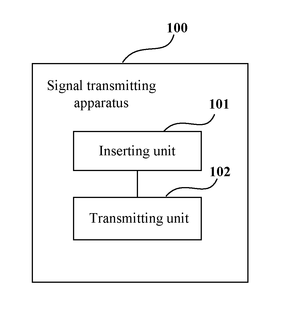
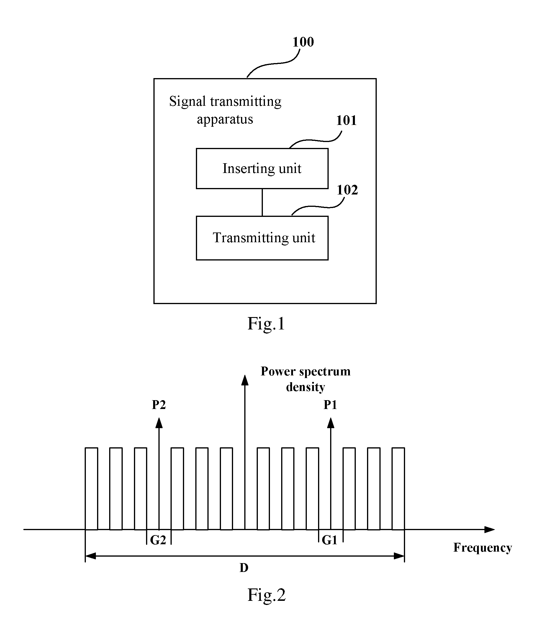
[0032]An embodiment of the present disclosure provides a signal transmitting apparatus used for an FDM system, which is applicable to a transmitter side of the FDM system. FIG. 1 is a schematic diagram of a structure of the signal transmitting apparatus of Embodiment 1 of the present disclosure. As shown in FIG. 1, the apparatus 100 includes: an inserting unit 101 and a transmitting unit 102.

[0033]The inserting unit 101 is configured to insert a pilot signal between neighboring subcarriers in a frequency domain, and the transmitting unit 102 is configured to transmit subcarrier signals with the pilot signal being inserted.

[0034]It can be seen from the above embodiment that by inserting a pilot signal between neighboring subcarriers at a transmitter side so as to calculate a laser phase noise according to a phase of the pilot signal at a receiver side, it is adapted for a frequency division multiplexing system having a high-order modulation format and a receiver having a high power s...

embodiment 2

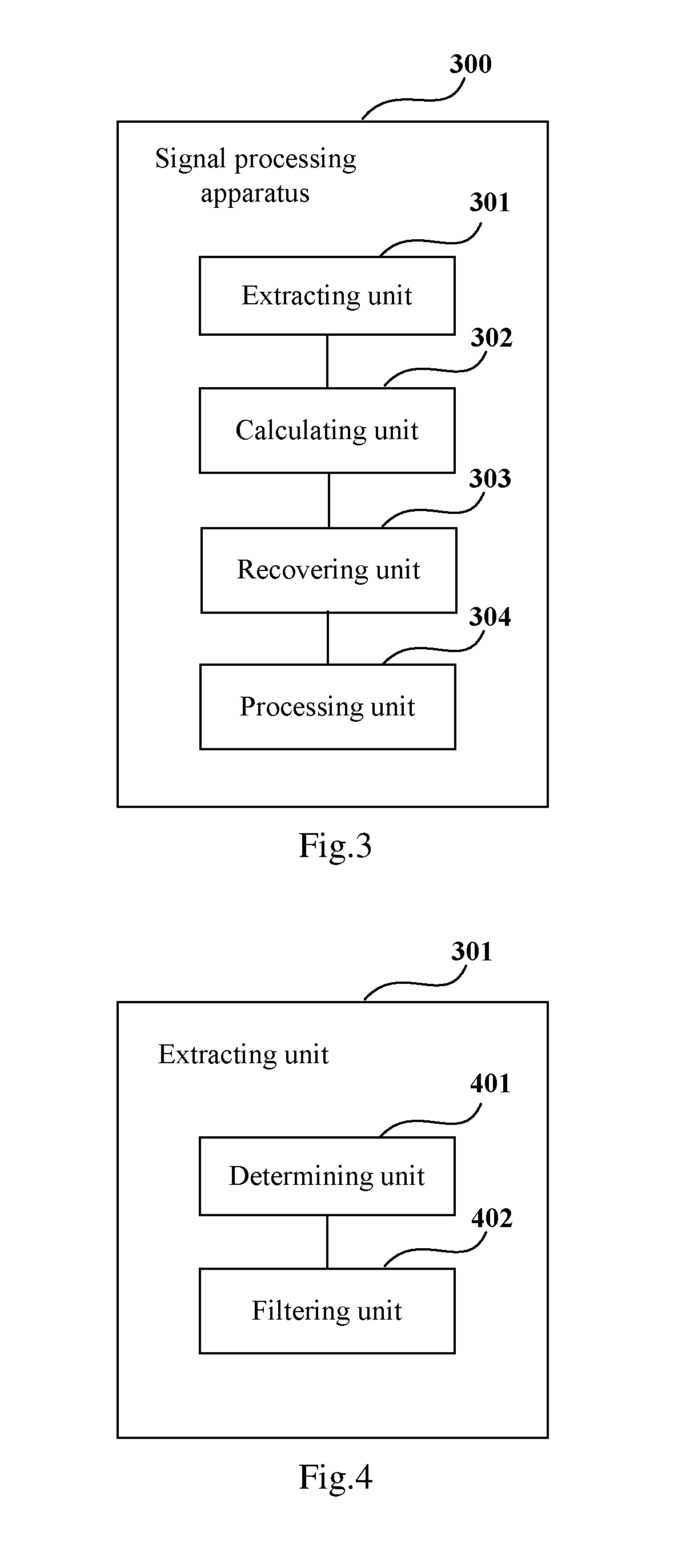
[0048]An embodiment of the present disclosure further provides a signal processing apparatus used for an FDM system, which is applicable to a receiver side of the FDM system. FIG. 3 is a schematic diagram of a structure of the signal processing apparatus of Embodiment 2 of the present disclosure. As shown in FIG. 3, the apparatus 300 includes: an extracting unit 301, a calculating unit 302, a recovering unit 303 and a processing unit 304.

[0049]The extracting unit 301 is configured to extract a pilot signal in received signals; the calculating unit 302 is configured to calculate a laser phase noise in the frequency division multiplexing system according to a phase of the pilot signal; the recovering unit 303 is configured to perform carrier phase recovery on the received signals according to the received signals and the laser phase noise; and the processing unit 304 is configured to perform down-sampling and equalization processing on the received signals after the recovering unit pe...

embodiment 3

[0071]An embodiment of the present disclosure further provides a transmitter. FIG. 6 is a schematic diagram of a structure of the transmitter of Embodiment 3 of the present disclosure. As shown in FIG. 6, the transmitter 600 includes a signal transmitting apparatus 601, a structure and functions of the signal transmitting apparatus 601 being identical to those described in Embodiment 1, and being not going to be described herein any further.

[0072]FIG. 7 is a block diagram of a systematic structure of the transmitter of Embodiment 3 of the present disclosure. As show in FIG. 7, the transmitter 700 includes: a signal generator 701, a signal setting unit 702, a digital-to-analog converting unit 703 and an optical modulator unit 704.

[0073]The signal generator 701 generates digital signals according to transmission data, the signal setting unit 702 inserts a pilot signal into the generated digital signals in the manner described in Embodiment 1, that is, inserting a pilot signal between ...


PUM


Abstract

Embodiments of the present disclosure provide a signal processing apparatus, a signal transmitting apparatus and a receiver, which are adapted for a frequency division multiplexing system having a high-order modulation format. A receiver having a high-magnification sampling rate by inserting a pilot signal between neighboring subcarriers at a transmitter side, calculating a laser phase noise according to a phase of the pilot signal at a receiver side, and performing down-sampling and equalization processing after performing carrier phase recovery according to the laser phase noise, so that a laser phase noise having a wide frequency may be accurately compensated, thereby having a relatively powerful carrier phase recovery ability.

Description

CROSS-REFERENCE TO RELATED APPLICATIONS[0001]This application claims the priority benefit of Chinese Patent Application No. 201510202004.2, filed on Apr. 24, 2015, in the Chinese State Intellectual Property Office, the disclosure of which is incorporated herein in its entirety by reference.BACKGROUND[0002]1. Field[0003]The present disclosure relates to the field of communications, and in particular to a signal processing apparatus, a signal transmitting apparatus and a receiver.[0004]2. Description of the Related Art[0005]As the development of optical communication technologies, the appearance of coherent receivers and high-speed digital signal processing (DSP) technologies push forward continuous increase of capacities of optical communication systems, conventional binary on-off keying (OOK) modulation formats are continuously upgraded, and quadrature phase shift keying (QPSK), 16QAM (quadrature amplitude modulation) and QAM formats of higher orders appear.[0006]On the other hand, ...

Claims


Application Information

Patent Timeline
IPC IPC(8): H04J1/02H04L27/26H04L5/00H04L27/00H04L27/01
CPCH04J1/02H04L27/0014H04L27/01H04L2027/004H04L27/2601H04L2027/0018H04L2027/0087H04L5/0048H04L27/2691H04L27/3863H04B10/548H04L27/2657H04L27/2672H04L27/2675H04L27/2697H04J14/0298H04J14/06H04B2210/075
Inventor DOU, LIANGTAO, ZHENNING
Owner FUJITSU LTD
Why Eureka
Try Eureka