Method for Predicting the Life of Transformer based on Fiber Grating Temperature Measurement System

a temperature measurement system and transformer technology, applied in the field of online monitoring of transformers, can solve the problems of difficult or even impossible to obtain actual testing, large error, and inability to meet the requirements of multi-line systems of transformers, and achieve the effect of improving safety and reliably the operation and maintenance strategies

Inactive Publication Date: 2016-11-03
TAIYUAN POWER SUPPLY COMPANY OF STATE GRID SHANXI ELECTRIC POWER +2
View PDF10 Cites 18 Cited by
  • Summary
  • Abstract
  • Description
  • Claims
  • Application Information

AI Technical Summary

Benefits of technology

[0038]The advantages of the present invention are as follows: the method according to the present invention is able to utilize a fiber grating temperature measuring system to calculate and evaluate the life loss of insulation in the inner side of the transformer and the changing rate thereof, so as to direct the operation and maintenance department for scientifically, safely and reliably improve the operation and maintenance strategies to the transformer. Through this system, the insulation aging degree in the transformer can be specifically assessed to the point. Based on the internal partial insulation position, the influence on the transformer of the insulation aging degree at the position is able to be judged, so as to scientifically and effectively describe the life of the transformer. Still further objects and advantages will become apparent from a consideration of the ensuing description and drawings.

Problems solved by technology

Since the transformer has a high voltage, high electromagnetic field environment at an inner side thereof, it is difficult or even impossible to obtain actual testing results through a traditional method of temperature measurement, so domestic and overseas scholars have carried out related researches long ago and achieved certain results.
It is not suitable for a transformer of a multi-line system.
The error is relatively large.
However, there are often relatively large errors during calculating in empirical models, especially when the top oil temperature of a large-capacity transformer lags far behind the oil temperature of the winding.
In this condition, this method can hardly reflect the rapid temperature changes of the winding and interturn oil ducts.
It hardly makes any sense to evaluate on the permitted overload and the operation life of the transformer.
However, the reflection is insufficient.
On the other hand, many parameters in the formulas are derived from the experience, which is not so universal and can impact the precision results.
The thermal simulation measurement method can only solve the value of the hot spot temperature, but cannot help to judge the exact location of the hot spots.
The direct detection for the temperature of the transformer cannot adopt a conventional electrical sensor temperature measuring system.
The infrared optical temperature measurement system can only be used to measure the surface temperature of an object, and cannot be used to measure the inner temperature of transformers of a complex structure.
To obtain the entire temperature information of a certain span, it is a waste of resources and also is difficult to use a single point mobile sensing method or a quasi-distributed sensing method which is composed of a plurality of single points.
From the current research result, the measurement error of the distributed fiber temperature measurement system is generally a few degrees Celsius, the positioning error thereof is about one meter.
For monitoring the internal temperature of the transformer, the positioning error is clearly large.

Method used


Image

  • Method for Predicting the Life of Transformer based on Fiber Grating Temperature Measurement System
  • Method for Predicting the Life of Transformer based on Fiber Grating Temperature Measurement System
  • Method for Predicting the Life of Transformer based on Fiber Grating Temperature Measurement System

Examples


Embodiment Construction

[0041]The following description is disclosed to enable any person skilled in the art to make and use the present invention. Preferred embodiments are provided in the following description only as examples and modifications will be apparent to those skilled in the art. The general principles defined in the following description would be applied to other embodiments, alternatives, modifications, equivalents, and applications without departing from the spirit and scope of the present invention.

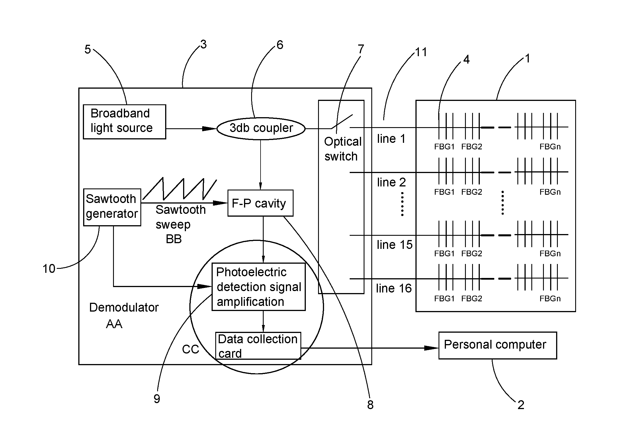
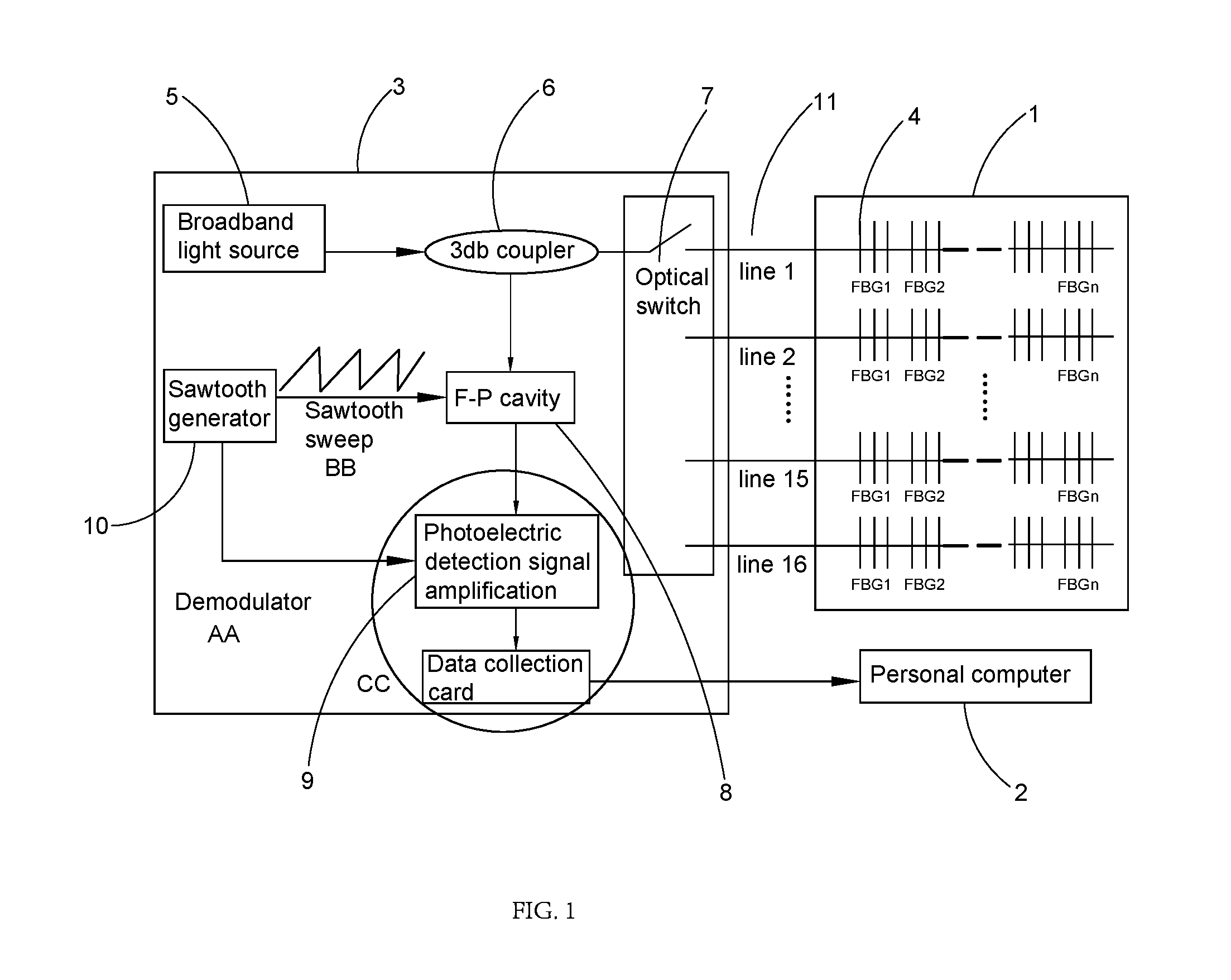
[0042]The reference characters in the drawings are illustrated as follows: 1—transformer body; 2—personal computer; 3—wavelength demodulator; 4—FBG sensors; 5—broadband light source; 6-3 dB coupler; 7—optical switch; 8—FP cavity; 9—photoelectric conversion module (photoelectric detection signal amplification); 10—sawtooth generator; 11—optical fiber.

[0043]The present invention adopts a fiber grating temperature measurement system to provide a quasi-distributed description of the internal temperat...


PUM

PropertyMeasurementUnit
fiber grating temperature measurementaaaaaaaaaa
central reflection wavelengthaaaaaaaaaa
peak wavelengthsaaaaaaaaaa

Abstract

A method for predicting the life of a transformer includes: conducting a quasi-distributed description on an internal temperature of a transformer by using a fiber grating temperature measurement system; determining the position of an internal hottest spot of the transformer and conducting a life evaluation on an internal local region of the transformer; and according to the life loss of each position of the transformer, by combining the insulation characteristic of the transformer with the influence of the life of the position on the entire life of the transformer, predicting the life of the transformer scientifically and reasonably. The method can use the fiber grating temperature measurement system to calculate and evaluate the life loss of the internal insulation of the transformer and the rate of change thereof

Description

NOTICE OF COPYRIGHT[0001]A portion of the disclosure of this patent document contains material which is subject to copyright protection. The copyright owner has no objection to any reproduction by anyone of the patent disclosure, as it appears in the United States Patent and Trademark Office patent files or records, but otherwise reserves all copyright rights whatsoever.BACKGROUND OF THE PRESENT INVENTION[0002]1. Field of Invention[0003]The present invention relates to a field of on-line monitoring of a transformer of a power transmission equipment, and more particularly to a method for detecting the actual temperature inside a transformer by a fiber grating temperature measurement system, evaluating and predicting the insulation life of a transformer according to the insulation properties of the transformer.[0004]2. Description of Related Arts[0005]The internal temperature of a power transformer is an important parameter to represent the thermal characteristics of the transformer a...

Claims


Application Information

Patent Timeline
Patent Type & Authority Applications(United States)
IPC IPC(8): G01N25/72G01R31/12G01K11/3206
CPCG01N25/72G01K11/3206G01R31/1227G01K2003/145G01R31/62
Inventor ZHANG, JUNLIUZHOU, GUOHUAXIONG, LIJUANGAO, XINXU, QIANGREN, JIANGONGWANG, SHANSHANLIANG, SIYUAN
Owner TAIYUAN POWER SUPPLY COMPANY OF STATE GRID SHANXI ELECTRIC POWER
Why Eureka
Try Eureka