Thermal compensated and tensed spring compact fiber bragg grating wavelength filter device

Active Publication Date: 2016-11-03
JINN HER ENTERPRISE
View PDF5 Cites 5 Cited by
  • Summary
  • Abstract
  • Description
  • Claims
  • Application Information

AI Technical Summary

Benefits of technology

[0013]The present invention includes two thermal-compensated mechanisms. The first thermal-compensated mechanism is the pre-stressing mechanism of FBG. The 0.9 mm outside diameter fiber-jacketing cylindrical compression coil spring 302, which is between the upper segment 301 and lower segment 303 of the 0.9 mm outside diameter fiber-jacketing cylindrical tension coil spring, is compressed at first; the compression coil spring 302 and two ends of the optical fiber grating in the axis are secured with the connecting rings or glues 304 and 305 and then released, whereby is completed the pre-stressing of FBG. The abovementioned structure is a new elasticity-based technology as a precision strain measurement for optical progression, wherein a cylindrical tension coil spring and a cylindrical compression coil spring jointly form a spring structure, and FBG is disposed in the axis of the cylindrical compression coil spring, and wherein the spring is compressed to fix the gauge length of FBG at first, and then the compressed spring is released, whereby is completed the pre-stressing of FBG. Within the elastic region, the behavior of material obeys the Hook's law, and the modulus of elasticity is used to set the pre-stressing linearly. The spring is compressed to fix FBG placed thereinside, and the then the applied force is released to complete the pre-stressing of FBG. Further, the compressed coil spring functions like a steel shell to protect the fragile FBG thereinside. The second thermal-compensated mechanism is releasing the pre-stres

Problems solved by technology

FBG that is not pre-loaded is unable to vary linearly with temperature change and likely to

Method used


Image

  • Thermal compensated and tensed spring compact fiber bragg grating wavelength filter device
  • Thermal compensated and tensed spring compact fiber bragg grating wavelength filter device
  • Thermal compensated and tensed spring compact fiber bragg grating wavelength filter device

Examples


Embodiment Construction

[0018]Below, embodiments are used to demonstrate the thermal-compensated fiber Bragg grating wavelength filter device whose optical fiber is jacketed by a low-thermal expansion coefficient tube in a loosely-jacketing technology.

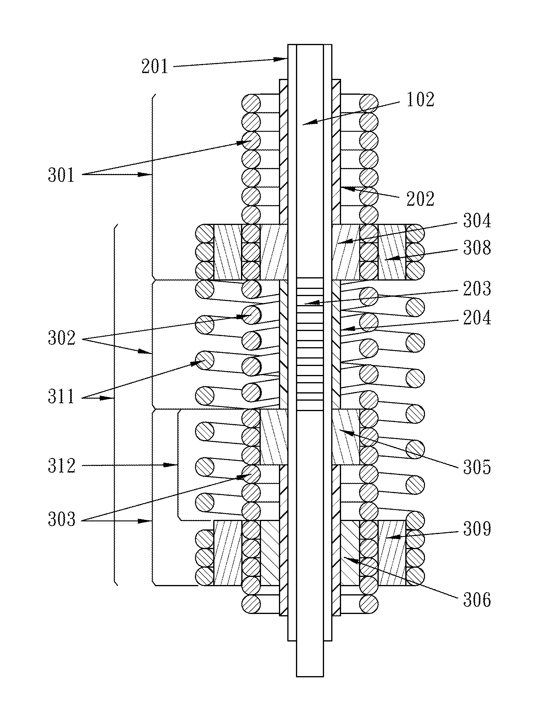
[0019]The thermal-compensated fiber Bragg grating wavelength filter device whose optical fiber is jacketed by a low thermal expansion coefficient second spring in a loosely-jacketing technology and wound in a different direction shown in FIG. 3 is normally used in a moisture-free and dust-free environment. While the thermal-compensated fiber Bragg grating wavelength filter device of the present invention is to be used in a moisture- and dust-containing environment, the present invention further proposes an embodiment, wherein a low thermal expansion coefficient tube jackets the structure of the thermal-compensated fiber Bragg grating wavelength filter device in a loosely-jacketing technology, as shown in FIG. 4. FIG. 4 is a cross-sectional diagrams schematica...


PUM


Abstract

A thermal-compensated fiber Bragg grating wavelength filter comprises an outer low thermal expansion coefficient metallic tube and an inner high thermal expansion coefficient cylindrical coil spring jacketed by the outer metallic tube and pre-stressed beforehand. The thermal-induced length difference of the outer metallic tube and the inner spring generates a stress-relieving effect or stress-increasing effect on the pre-stressed high thermal expansion coefficient cylindrical coil spring, whereby to increase or decrease the refractive index and compensate for the thermal-induced wavelength shift of the fiber Bragg grating.

Description

FIELD OF THE INVENTION[0001]The present invention relates to a wavelength filter device, particularly to a precision wavelength filter device whose fiber Bragg grating is jacketed and pre-stressed by springs to achieve a thermal-compensated function.BACKGROUND OF THE INVENTION[0002]A fiber Bragg grating (abbreviated as FBG below) is formed by an optical fiber to function as a precision wavelength filter for optical fiber communication, which reflects the light wave according to the Bragg feedback wavelength λB determined by the predetermined Bragg grating period Λ of the fiber grating. Based on the principle of Bragg diffraction, a wavelength meeting the Bragg condition is called a Bragg feedback wavelength κB; the light wave having a Bragg feedback wavelength will be reflected in a direction opposite the incident direction to a scanning device Interrogator emitting the incident light for analysis, whereby to detect whether the received wavelength changes and whereby the reflected l...

Claims


Application Information

Patent Timeline
IPC IPC(8): G02B6/02
CPCG02B6/0218G02B6/02176G02B6/022G02B6/29322G02B6/29398
Inventor TSAI, YUNG-YUYANG, CHUN-CHU
Owner JINN HER ENTERPRISE
Why Eureka
Try Eureka