Optimized Grid Design for Concentrator Solar Cell

a concentrator and solar cell technology, applied in the field of concentrator solar cells, can solve the problems of low efficiency, high current density, and often at odds with conductivity and transparency requirements, and achieve the effect of increasing power outpu

Active Publication Date: 2016-11-03
IBM CORP +1
View PDF9 Cites 18 Cited by
  • Summary
  • Abstract
  • Description
  • Claims
  • Application Information

AI Technical Summary

Problems solved by technology

These requirements for conductivity and transparency are often at odds with one another.
For instance, a thicker grid design leads to better conductivity but reduced transparency, and vice versa.
The current density is very high and appreciable power can be lost in the grid resistance.
The further the carriers travel along the grid to reach the bus, the greater the resistive power loss is.
With conventional grid designs the loss due to resistance is still undesirably high.

Method used


Image

  • Optimized Grid Design for Concentrator Solar Cell
  • Optimized Grid Design for Concentrator Solar Cell
  • Optimized Grid Design for Concentrator Solar Cell

Examples


Embodiment Construction

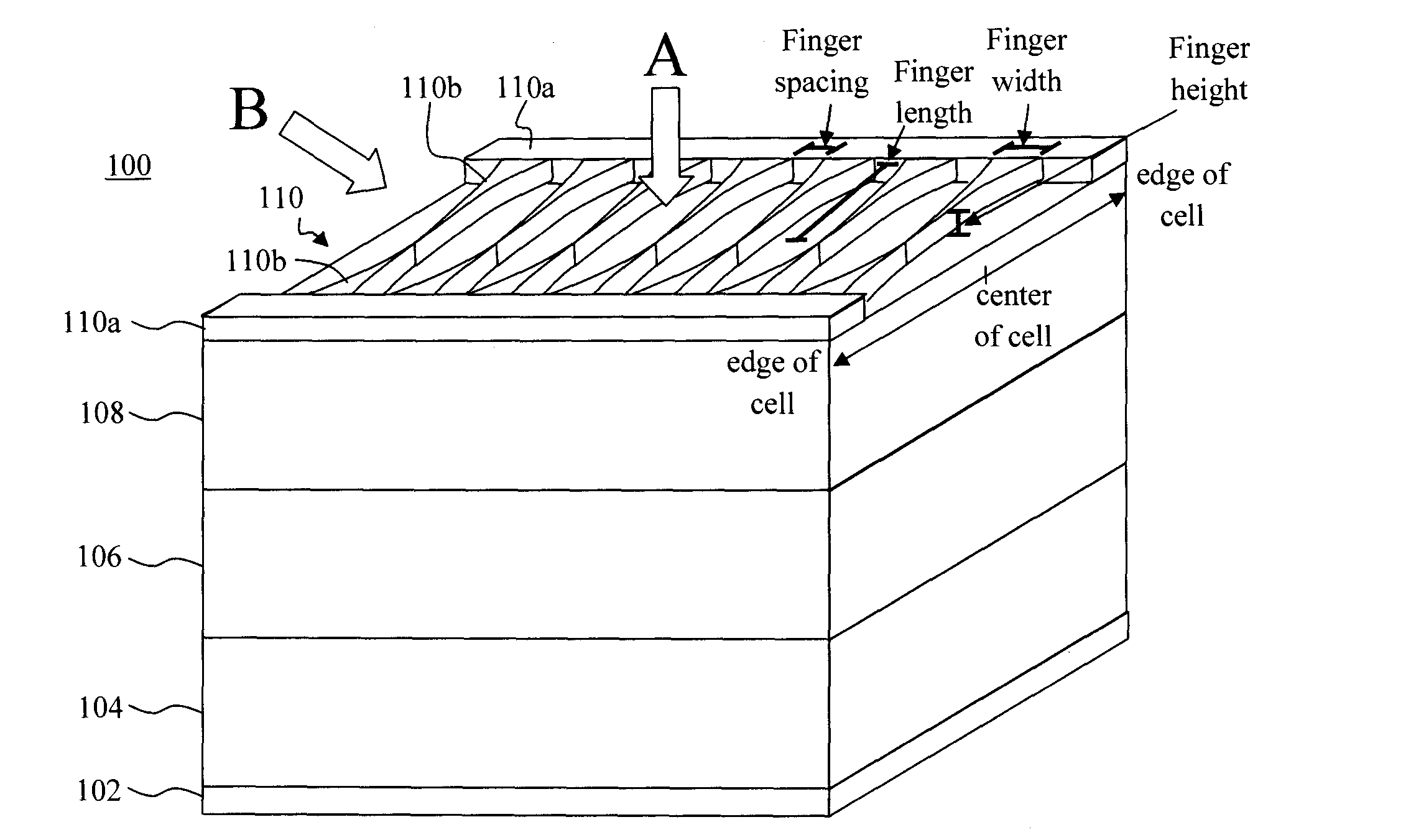
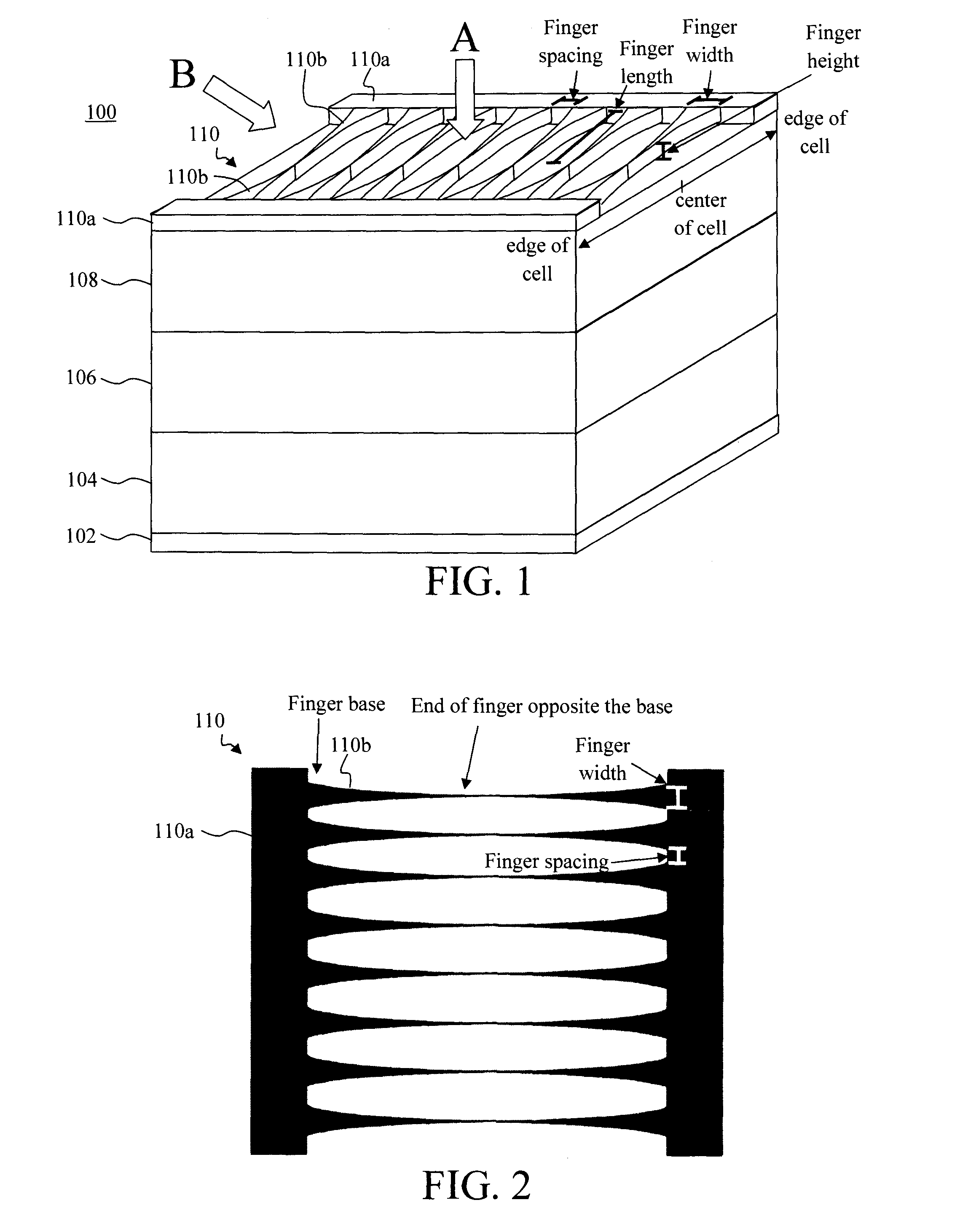
[0024]Provided herein are concentrator solar cell top contact grid pattern designs which provide increased power output compared to conventional grid patterns for a given cell size, while maximizing transparency. With regard to transparency, as highlighted above the top contact generally consists of a metal grid on top of the light absorbing layers of the device. The metal grid shadows / blocks a portion of the top surface of the device, and thus cuts down the amount of photons received by the semiconductor layers below the grid due to shadowing. The transparency of the device is thus a factor of how much of the top surface is blocked by the metal grid. With regard to transparency, the thinner the grid design the better. However, sufficient electrical conductivity favors a thicker grid design. When the metal grid design is too thin, the losses due to resistance are unacceptably large.

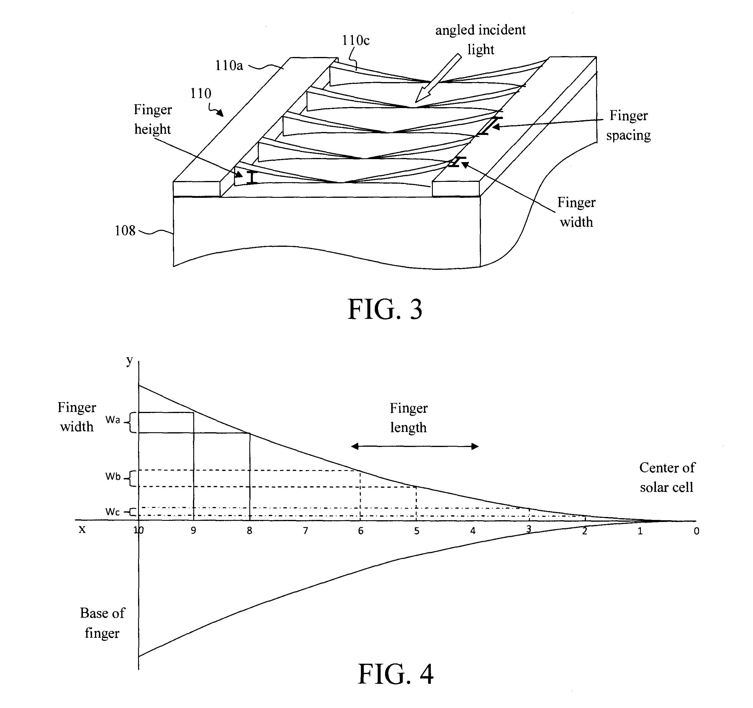
[0025]Advantageously, the present techniques optimize the shape of the metal lines of the grid design ...


PUM


Abstract

Grid patterns for concentrator solar cells that increase power output are provided. In one aspect, a top contact for a solar cell is provided that includes: bus connectors and metallic fingers attached to the bus connectors, wherein each of the metallic fingers has a base which is connected to one of the bus connectors or to another one of the metallic fingers such that each of the metallic fingers is attached to one of the bus connectors either directly or indirectly via another one of the metallic fingers, and wherein at least one of the metallic fingers has a width that is tapered quadratically along a length of the metallic finger. A solar cell and a method of forming a solar cell top contact are also provided.

Description

FIELD OF THE INVENTION[0001]The present invention relates to concentrator solar cells and more particularly, to grid pattern designs for concentrator solar cells that increase power output.BACKGROUND OF THE INVENTION[0002]Photovoltaic solar cells often include a top contact which consists of a metal grid on top of the light absorbing layers of the device. The design of the grid is such that it must be sufficiently electrically conductive yet permit enough light to pass to the underlying cell. These requirements for conductivity and transparency are often at odds with one another. For instance, a thicker grid design leads to better conductivity but reduced transparency, and vice versa.[0003]At high solar concentrations, the design of a photovoltaic solar cell grid is important for maximum energy conversion efficiency. The current density is very high and appreciable power can be lost in the grid resistance. Conventional grid designs often include a simple symmetrical pattern consisti...

Claims


Application Information

Patent Timeline
Patent Type & Authority Applications(United States)
IPC IPC(8): H01L31/02
CPCH01L31/0201Y02E10/50H01L31/022425H01L31/022433
Inventor MARTIN, YVES C.SALHI, ABDELMAJIDVAN KESSEL, THEODORE G.
Owner IBM CORP
Why Eureka
Try Eureka