
Rotary capacitor for shunting high frequency bearing currents and reducing EMI in electric machinery

Active Publication Date: 2016-11-10
C MOTIVE TECHNOLOGIES INC
View PDF5 Cites 18 Cited by
  • Summary
  • Abstract
  • Description
  • Claims
  • Application Information

AI Technical Summary

Benefits of technology

This patent provides a way to prevent damage to machine bearings caused by high-frequency electrical currents. It does this by using a non-contact method to reduce or mitigate the flow of such currents through the bearings, which can cause mechanical wear and electomagnetic interference. This results in longer life and better performance of the bearings.

Problems solved by technology

Bearing currents are undesirable due to the adverse wear they cause.
When electric current flows through this capacitor, electric potentials develop across the bearing surfaces and can arc, causing pitting.
Pitting of the bearing surfaces causes mechanical wear and premature failure of the bearing 50.
Bearing failure is catastrophic for electric machinery, and failure will often propagate to systems attached to the machine 10, such as gearboxes, turbines, impellers, etc.
Electromagnetic interference may also result from parasitic coupling due to the parasitic voltage on the shaft.
However, brushes experience significant mechanical wear and accumulate brush dust over time, requiring periodic maintenance.
However, drawbacks of this system include the higher purchase price for ceramic bearings, and the need for significant downtime / effort to undertake the difficult task of retrofitting existing / deployed systems.
Line filters can be expensive and bulky, deterring their deployment in many applications.
Additionally, line filters are most often passive (i.e., have constituent components with fixed values), thereby limiting the adaptability of line filters in a changing environment.
What is needed is a device and method that will simultaneously reduce or mitigate bearing currents and electromagnetic interference without the above drawbacks, such as the need for periodic maintenance, higher costs, and limited adaptability.

Method used


Image

  • Rotary capacitor for shunting high frequency bearing currents and reducing EMI in electric machinery
  • Rotary capacitor for shunting high frequency bearing currents and reducing EMI in electric machinery
  • Rotary capacitor for shunting high frequency bearing currents and reducing EMI in electric machinery

Examples


Embodiment Construction

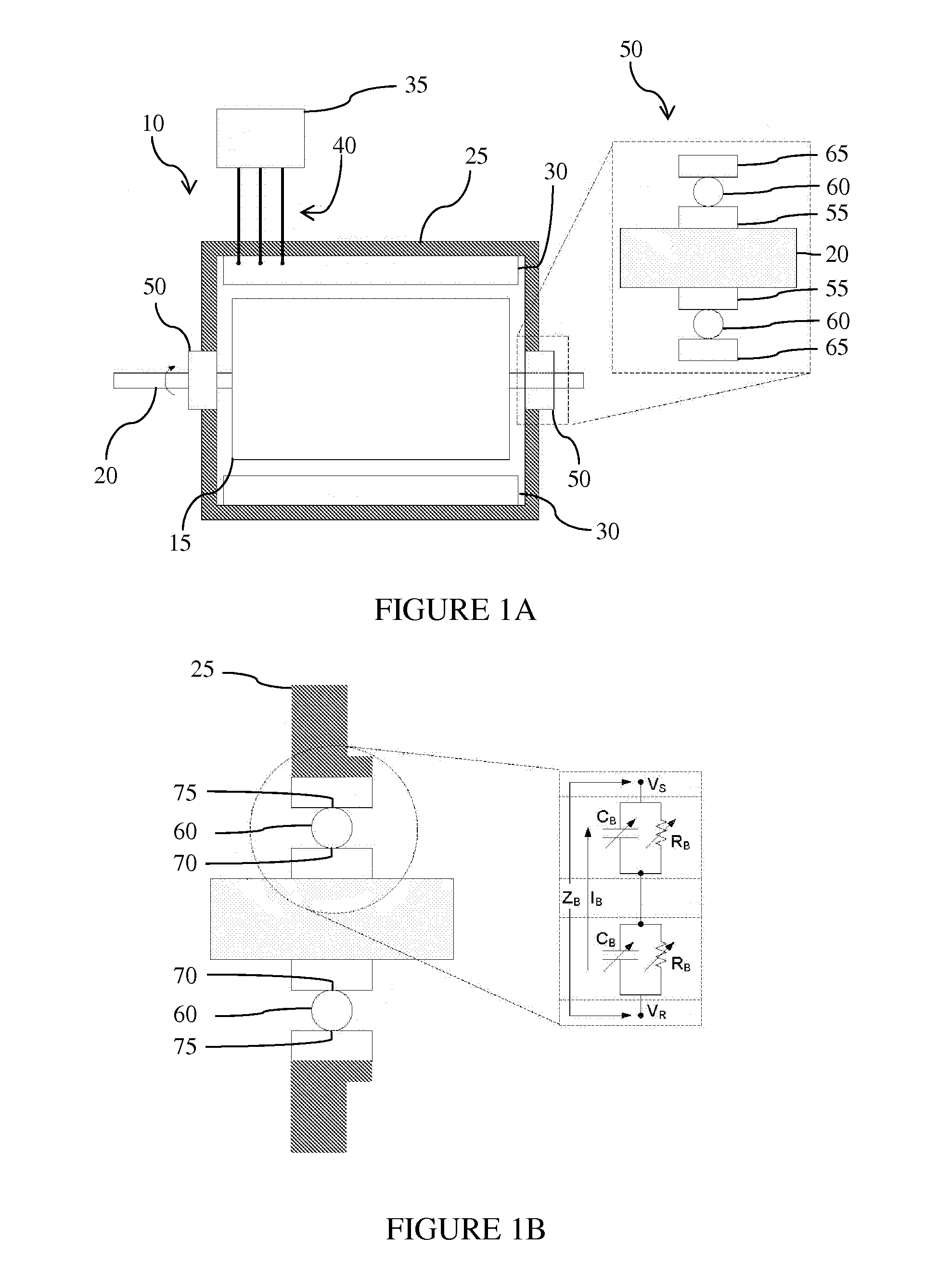
[0022]Continuing the discussion started in the “Summary,” in FIGS. 1A and 1B, the rotor 15 of the electric machine 10 is supported by the stator frame 25 via ball bearings 50 at each end of the machine 10. The stator frame 25 also supports the stator windings 30 that surround the rotor 15. The magnified view of the ball bearing 50 shows that the bearings 50 include inner and outer races 55, 65 separated by balls 60, which are typically made of a hard conducting material such as steel. The inner race 55 of the ball bearing 50 is pressed against the shaft 20, and the outer race 65 rests within one end of the stator frame 25. The races 55, 65 are held concentric by the balls 60, allowing the inner race 55 to rotate. A power electronic (variable frequency) drive 35 provides line frequency 40 (such as 60 Hz) power, but also supplies high frequency components that create undesirable bearing currents.

[0023]The points at which the balls 60 make contact with the inner and outer races 55, 65 ...


PUM


Abstract

Rotary capacitor assemblies divert or mitigate high-frequency electrical currents and voltages in bearings of electric machinery (e.g., motors and generators) without direct contact with the bearings. The assemblies include rotating capacitors, in which surfaces in close proximity are free to rotate with respect to another while maintaining relative surface area and separation distance. A lubricant (such as air or oil) facilitates capacitive surfaces hydrodynamically “floating” on each other. A shunt body is connected electrically in parallel with the bearings of the machine, providing a non-contact or nearly non-contact electrical pathway for damaging high-frequency currents an voltages to be shunted around the mechanical load carrying bearings.

Description

CROSS-REFERENCE TO RELATED APPLICATIONS[0001]This application claims priority under 35 USC §119(e) to U.S. Provisional Patent Applications 61 / 936,190 filed Feb. 5, 2014, 62 / 044,443 filed Sep. 2, 2014, and 62 / 063,068 filed Oct. 13, 2014, the entireties of which are incorporated by reference herein.FIELD OF THE INVENTION[0002]This document concerns an invention relating generally to the use of rotary capacitors in a variety of configurations to form an electrical connection to the shaft of an electric machine to mitigate electric currents flowing through shaft bearings.BACKGROUND OF THE INVENTION[0003]A motor, generator, gearbox, turbine, impeller, and other devices having (or attached to) rotating or translating shafts may be termed an “electric machine,” or collectively termed “electric machinery.” Referring to the exemplary electric motor / generator and bearings shown in FIGS. 1A and 1B, electric machine 10 is often connected to an electrical source or load via power electronics 35....

Claims


Application Information

Patent Timeline
IPC IPC(8): H02K11/028H02K11/40
CPCH02K11/40H02K11/028H02K11/0094
Inventor REED, JUSTIN KYLELUDOIS, DANIEL COLINMASON, WILLIAM P.WOLF, DONALD
Owner C MOTIVE TECHNOLOGIES INC
Learn More