Radiation dosage monitoring system

a technology of radiation dosage and monitoring system, which is applied in the field of radiation dosage monitoring system, can solve the problems of the complexity of the treatment plan for the application of radiotherapy, and achieve the effects of reducing the overall treatment time, increasing the possibility of mistreatment, and increasing radiation levels

Active Publication Date: 2016-11-17
VISION RT LTD
View PDF3 Cites 11 Cited by
  • Summary
  • Abstract
  • Description
  • Claims
  • Application Information

AI Technical Summary

Benefits of technology

[0018]Another problem associated with monitoring patients during radiotherapy treatments is the fact that the appearance of the Cherenkov radiation emitted from a patient undergoing radiotherapy is dependent on the skin tone or color, more specifically, on the level of chromophores present in the skin of the patient. The two chromophores which are of greatest significance are blood and melanin. This has the effect that any estimate of radiation received by the patient could be either too high or too low if the level of chromophores in the skin is not taken into account when determining that estimate. It will be understood that an incorrect estimation of the levels of radiation received by the patient estimate can have serious consequences to the well-being of the patient as it is the estimates which are used to determine compliance with a radiation treatment plan which has been calculated to deliver the correct levels of radiation to the patient. Too low an estimate will result in increased levels of radiation being applied to comply with the treatment plan and lead to possible damage to the patient's tissue. Conversely, too low an estimate will result in not enough radiation being applied to the patient and lead to incomplete irradiation of the tumor being treated. This is particularly important as it has already been stated above that there is an increasing trend to make use of higher doses of radiation during treatment in order to reduce overall treatment time, with such higher dosages bringing with them the increasing possibility of mistreatment.

Problems solved by technology

Treatment plans for the application of radiotherapy are becoming increasingly complex with treatment apparatus having multiple or floating iso-centers.
Such increasing complexity and higher dosages bring with them the increasing possibility of mistreatment.

Method used


Image

  • Radiation dosage monitoring system
  • Radiation dosage monitoring system
  • Radiation dosage monitoring system

Examples


Embodiment Construction

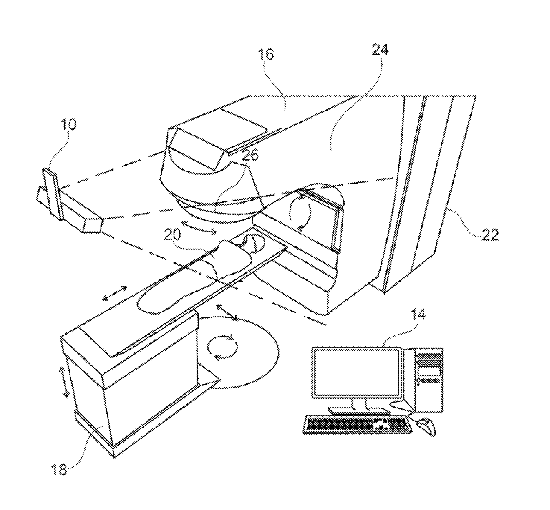
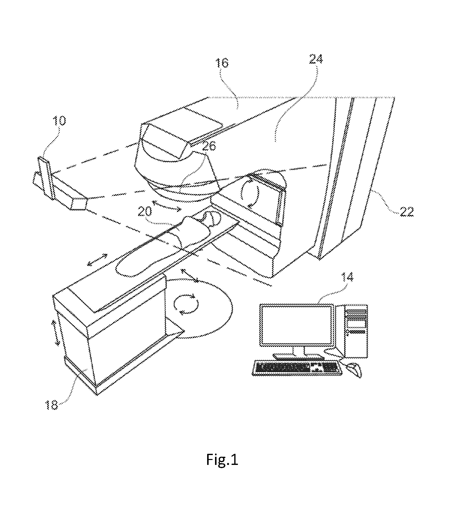
[0028]FIG. 1 is a schematic perspective view of an embodiment of a radiation dosage monitoring system in accordance with an embodiment of the present invention.

[0029]The radiation dosage monitoring system comprises a stereoscopic camera system 10 that is connected by wiring (not shown) to a computer 14. The computer 14 is also connected to treatment apparatus 16 such as a linear accelerator for applying radiotherapy. A mechanical couch 18 is provided as part of the treatment apparatus upon which a patient 20 lies during treatment. The treatment apparatus 16 and the mechanical couch 18 are arranged such that, under the control of the computer 14, the relative positions of the mechanical couch 18 and the treatment apparatus 16 may be varied, laterally, vertically, longitudinally and rotationally as is indicated in the figure by the arrows adjacent the couch.

[0030]The treatment apparatus 16 comprises a main body 22 from which extends a gantry 24. A collimator 26 is provided at the end ...


PUM


Abstract

Some embodiments are directed to a radiation dosage monitoring system including a model generation module configured to generate a 3D surface model of a portion of a patient undergoing radiation treatment, an image detector configured to detect Cherenkov radiation and any subsequent secondary and scattered radiation originating due to the initial Cherenkov radiation emitted from the patient, a processing module configured to determine estimations of radiation applied to the patient utilizing the images from the image detector and the 3D model, and to utilize the determined estimations of radiation applied to the patient together with data indicative of the orientation of a radiation beam inducing emission of the Cherenkov radiation at a time when the radiation beam was applied to generate a 3D internal representation of the location of the portions of a irradiated patient resulting in the emission of the Cherenkov radiation.

Description

CROSS REFERENCE TO RELATED APPLICATION[0001]This application claims the priority benefit under 35 U.S.C. §119 of British Application No.: 1508104.5, filed on May 12, 2015, and British Application No.: 1605424.9, filed on Mar. 31, 2016, the contents of which are hereby incorporated in their entireties by reference.FIELD OF THE INVENTION[0002]The present invention concerns a radiation dosage monitoring system. In particular, embodiments of the present invention concern a radiation dosage monitoring system for monitoring radiation dosages applied to a patient undergoing radiation treatment.BACKGROUND TO THE INVENTION[0003]Radiotherapy consists of projecting onto a predetermined region of a patient's body, a radiation beam so as to destroy or eliminate tumors existing therein. Such treatment is usually carried out periodically and repeatedly. At each medical intervention, the radiation source must be positioned with respect to the patient in order to irradiate the selected region with t...

Claims


Application Information

Patent Timeline
Patent Type & Authority Applications(United States)
IPC IPC(8): A61N5/10G06T7/00G06T15/04H04N13/02
CPCA61N5/1071H04N13/0246G06T7/0012A61N2005/1085G06T7/004G06T2200/04G06T2207/30244G06T15/04A61N5/1048A61N5/1075G01T1/29A61N2005/1059A61N2005/1072A61B5/0071G01T1/22G06T7/85H04N13/246A61B6/582A61N5/1049A61N5/1064A61B6/00A61N2005/0627A61N2005/0628
Inventor HALE, GIDEON MATTHEWMEIR, IVAN DANIELPAWLICKI, TODDALLEN, MARTIN
Owner VISION RT LTD
Why Eureka
Try Eureka