
Tyre apparatus

Active Publication Date: 2016-11-17
PERKINS ENGINES
View PDF7 Cites 13 Cited by
  • Summary
  • Abstract
  • Description
  • Claims
  • Application Information

AI Technical Summary

Benefits of technology

The patent text is stating that the inner chamber of a vehicle's tire can provide protection in case of a sudden pressure loss. This is because the inner chamber has superior structural qualities.

Problems solved by technology

This is particularly important in the road haulage industry where fuel represents a significant percentage of HGV operating costs.

Method used


Image

  • Tyre apparatus
  • Tyre apparatus
  • Tyre apparatus

Examples


Embodiment Construction

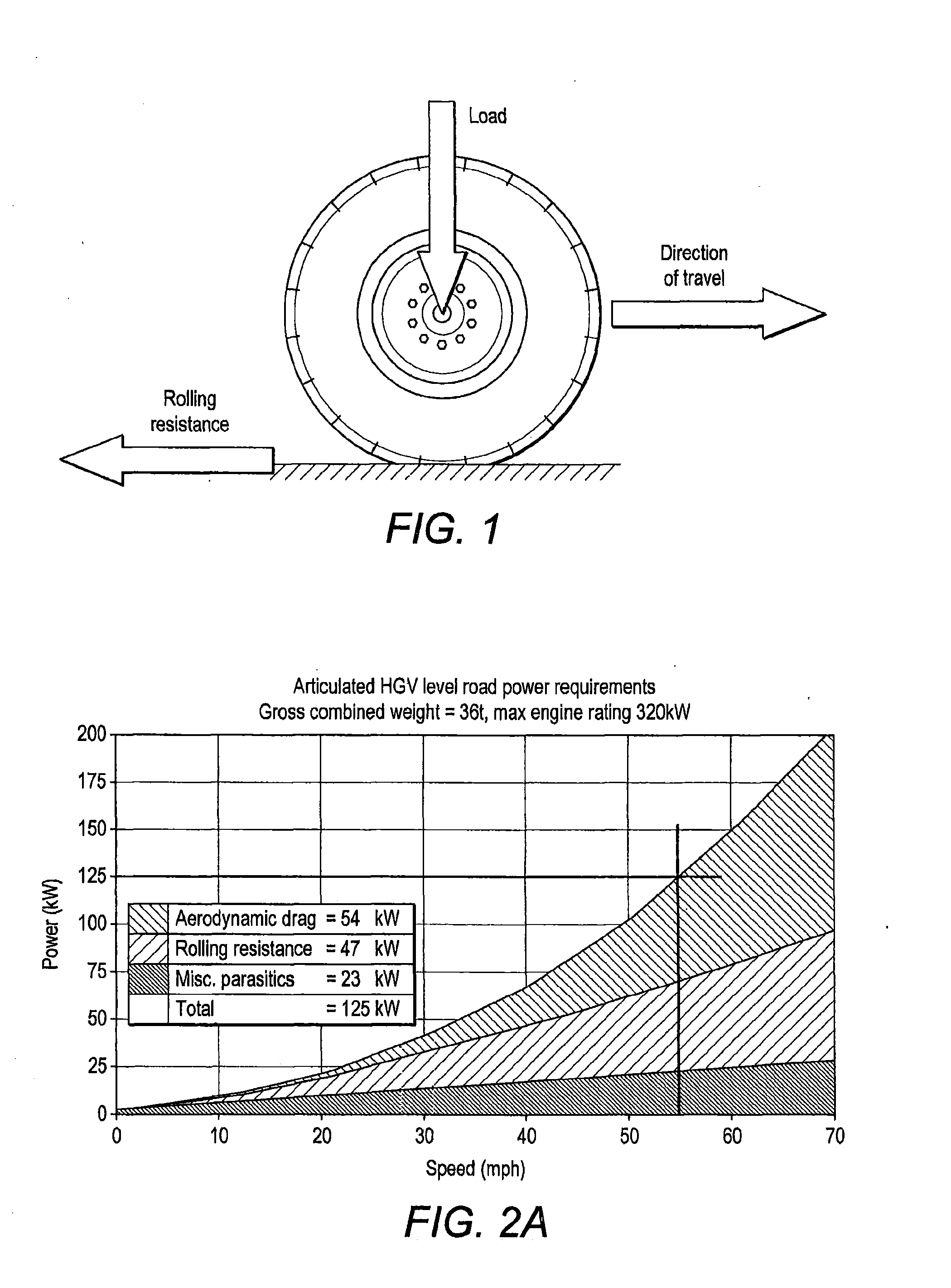
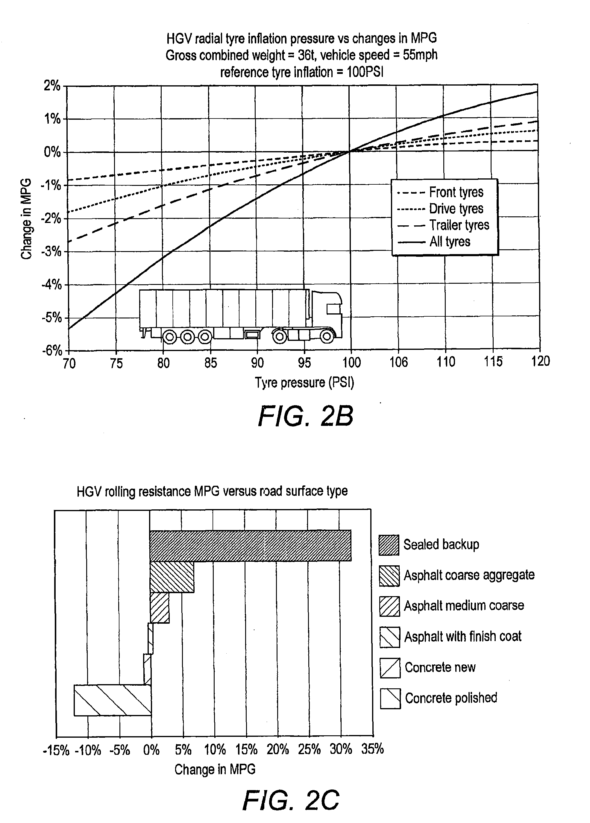
[0035]FIG. 2a illustrates the significant contribution (circa. 38% @ 55 mph) that rolling resistance makes to the overall power losses experienced in a reference HGV vehicle having a gross weight of 32,000 kg and a maximum power rating of 320 kW. FIG. 2b illustrates the effect that tyre inflation pressure can have on fuel efficiency and, in particular, the extent by which under or over-inflation of tyres at different positions on a reference HGV vehicle can influence its overall fuel efficiency. FIG. 2c shows how various different types of a road surface can influence fuel efficiency. FIG. 2d illustrates the linear relationship between typical air losses in an HGV vehicle tyre over time.

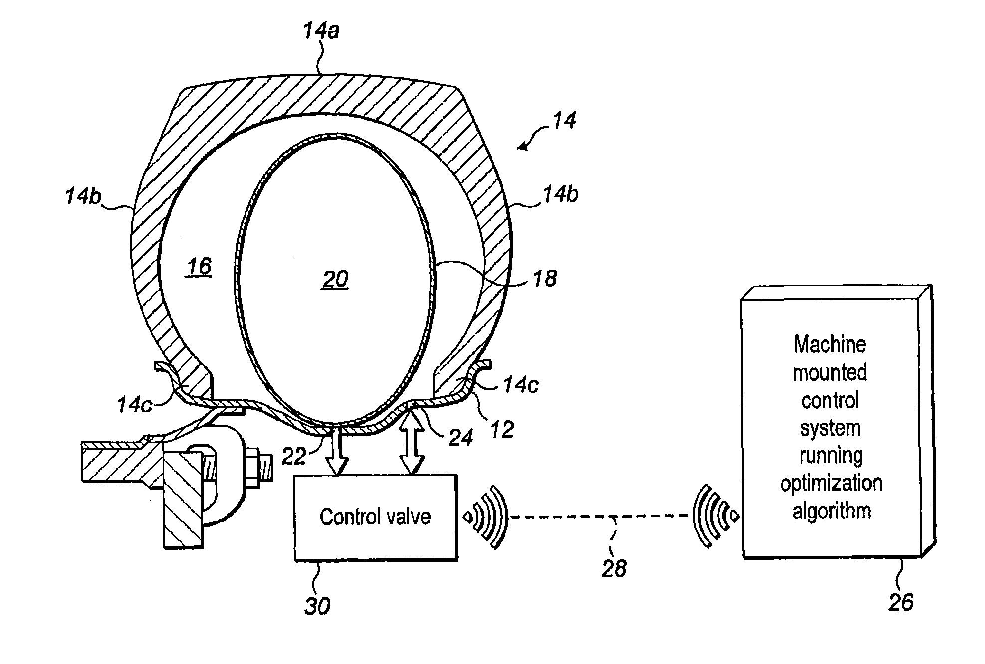
[0036]FIG. 3 is a cross-sectional schematic representation of the tyre apparatus 10 of the present disclosure connected to a wheel rim 12 of a vehicle (not shown). The tyre apparatus includes a tyre body 14 having a tread portion 14a, two sidewall portions 14b, and two bead portions 14c. The bead por...


PUM


Abstract

A tyre apparatus is provided, the apparatus including a tyre body for attachment to a wheel rim to define a first inflatable volume. An inner chamber defines a second inflatable volume which is located within the first inflatable volume of the tyre body. A first fluid communication path is provided between the first and second inflatable volumes and a second fluid communication path is provided between the first inflatable volume and the atmosphere. A first valve opens and closes the first fluid communication path, and a second valve opens and closes the second fluid communication path. The tensile strength and pressure-containing capacity of the material structure of the second inflatable volume is greater than that of the tyre first inflatable volume. A first fluid pressure within the first inflatable volume of the tyre body is optimisable by opening the first valve to allow pressure transfer from the second inflatable volume into the tyre body, and / or opening the second valve to allow pressure to vent from the tyre body to atmosphere. A vehicle wheel and active tyre pressure control system incorporating the tyre apparatus are also provided.

Description

[0001]The present disclosure relates generally to a tyre apparatus for heavy duty vehicles (HDVs). More particularly, the present disclosure relates to a wheel-mountable tyre comprising an inner chamber which is inflatable independently of an outer ground-engageable tyre body. A vehicle wheel incorporating the tyre apparatus; and an active tyre pressure control system incorporating the vehicle wheel are also disclosed.BACKGROUND OF THE INVENTION[0002]Vehicle manufacturers continually invest in research and development efforts aimed at improving the fuel efficiency of road vehicles. This is particularly important in the road haulage industry where fuel represents a significant percentage of HGV operating costs. Fuel efficiency is dependent on numerous different factors other than the inherent efficiency of engines. For example, aerodynamic styling features such as cab roof deflectors, air dams, side skirts etc. help to reduce aerodynamic drag with consequent improvements to overall f...

Claims


Application Information

Patent Timeline
IPC IPC(8): B60C5/22B60C23/00B60C17/01
CPCB60C5/22B60C2200/06B60C23/004B60C17/01B60C5/20
Inventor STRASHNY, IGORMOORE, PAUL
Owner PERKINS ENGINES
Learn More