
Supply of air to an air-conditioning circuit of an aircraft cabin from its turboprop engine

a technology of air conditioning circuit and aircraft cabin, which is applied in the direction of machines/engines, liquid fuel engines, machine/engines, etc., can solve the problems of requiring specific de-icing means and generating turbulence in the airflow of the coke, so as to reduce the temperature of the air sent to the aircraft, simplify the precooler, and the effect of compactness

Active Publication Date: 2016-11-17
SAFRAN POWER UNITS +2
View PDF6 Cites 14 Cited by
  • Summary
  • Abstract
  • Description
  • Claims
  • Application Information

AI Technical Summary

Benefits of technology

The patent describes a turboprop engine that does not require an air-takeoff scoop that generates turbulence and requires special de-icing means. Instead, the engine uses a pneumatic starter that is connected to an air inlet pipe for starting. This allows for a more efficient and reliable starting process. The invention also suggests using the air-conditioning circuit's pipes to supply air to the pneumatic starter, which can improve engine performance during certain stages of operation.

Problems solved by technology

This type of scoop has the drawback of generating turbulence in this airflow and of requiring specific de-icing means.

Method used


Image

  • Supply of air to an air-conditioning circuit of an aircraft cabin from its turboprop engine
  • Supply of air to an air-conditioning circuit of an aircraft cabin from its turboprop engine
  • Supply of air to an air-conditioning circuit of an aircraft cabin from its turboprop engine

Examples


Embodiment Construction

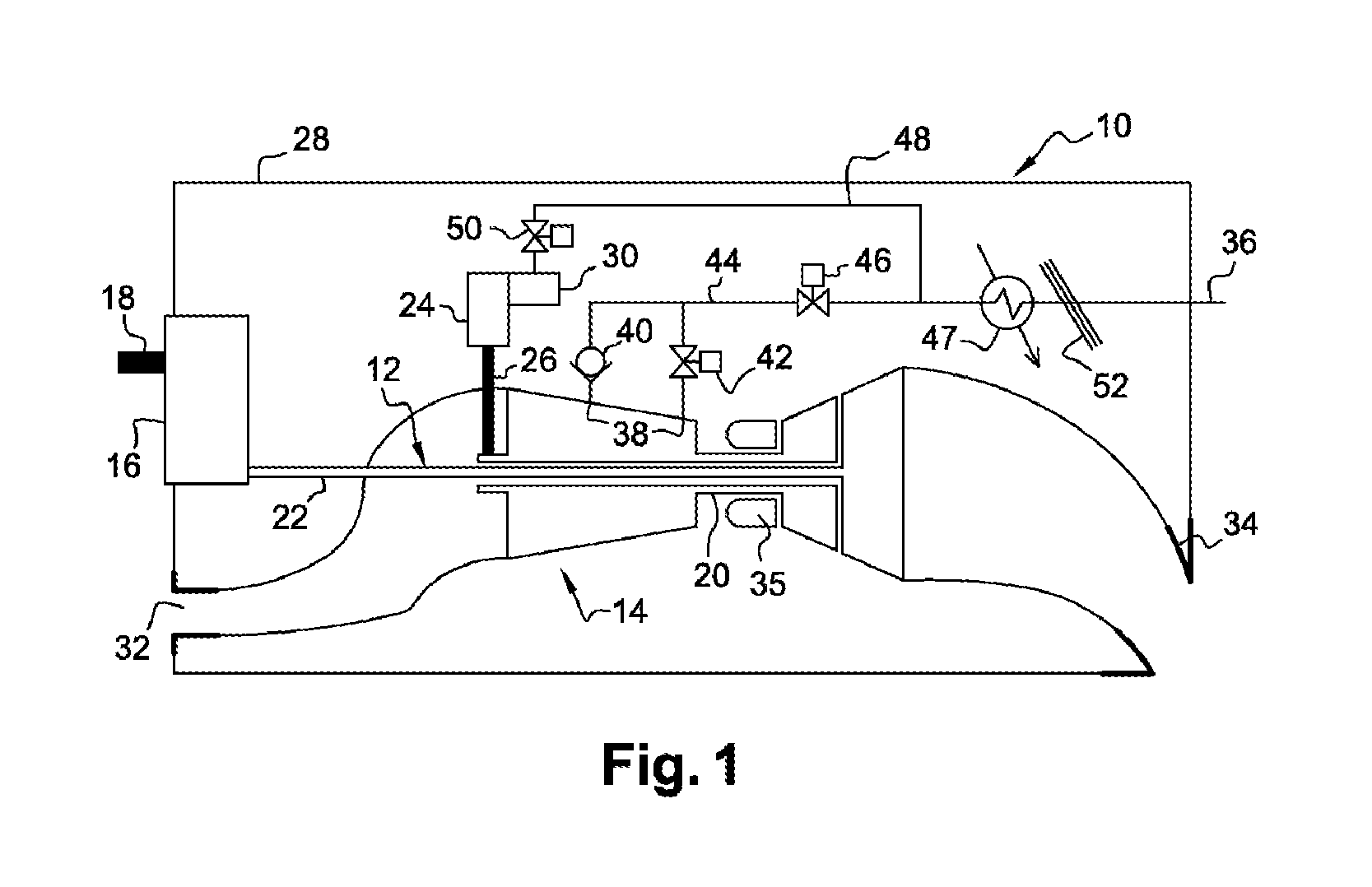
[0037]Reference is made first of all to FIG. 1, which depicts a turboprop engine 10 according to the prior art, for an aircraft.

[0038]In this case, the turboprop engine 10 is of the double-body type and comprises a low-pressure body 12 and a high-pressure body 14, the low-pressure body 12 driving a propulsion propeller by means of a gearbox 16 or reduction gearbox, usually referred as a PGB (power gearbox). Only the shaft 18 of the propulsion propeller is shown in FIG. 1.

[0039]In this case, the low-pressure body 12 comprises only a turbine rotor connected by a shaft to the gearbox 16. The high-pressure body 14 comprises a compressor rotor connected by a shaft to a turbine rotor. The shaft of the high-pressure body 14, referred to as HP shaft 20, is tubular and has the shaft of the low-pressure body 12, referred to as the LP or power shaft 22, passing coaxially therethrough. The LP shaft 22 comprises at one end a pinion (not shown) coupled by means of a series of pinions of the gearb...


PUM


Abstract

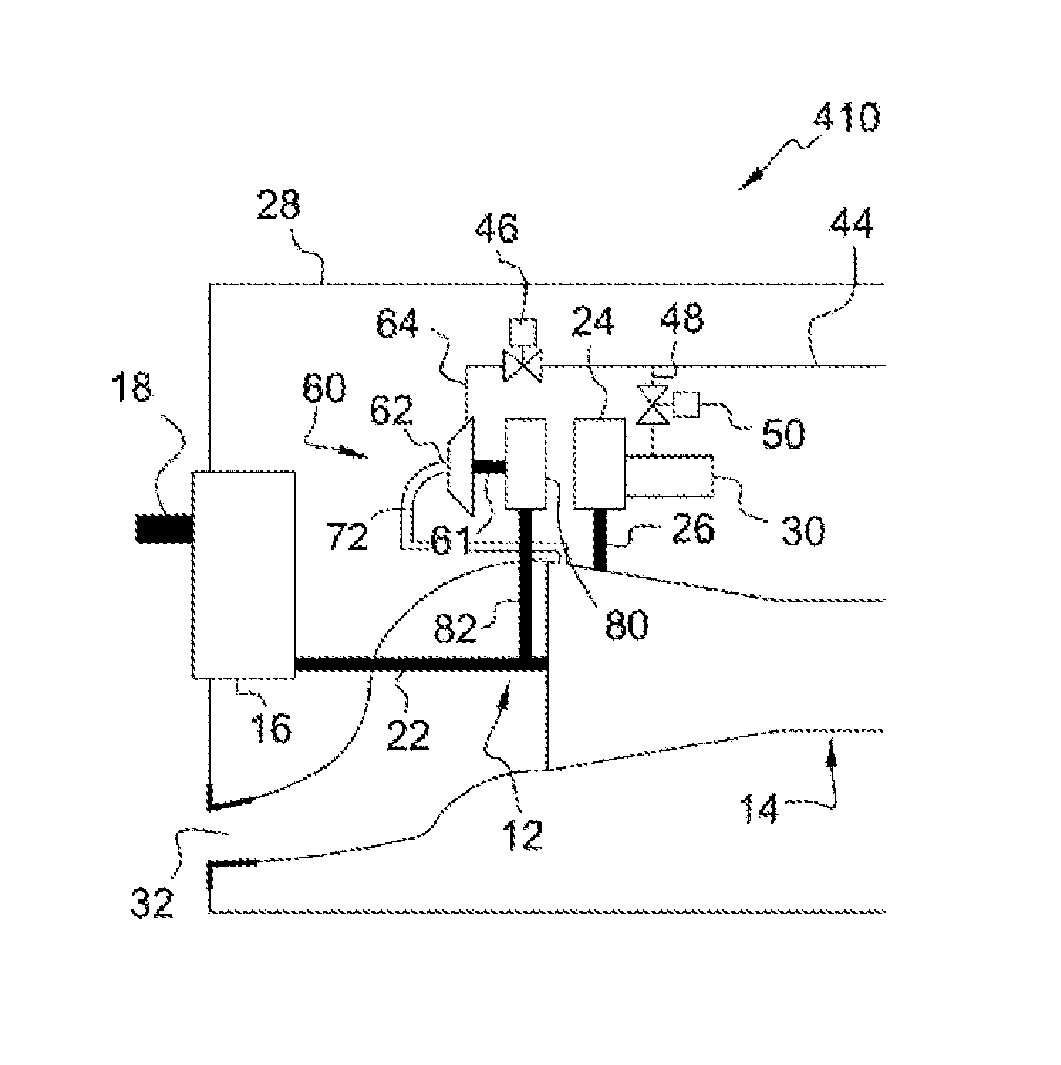
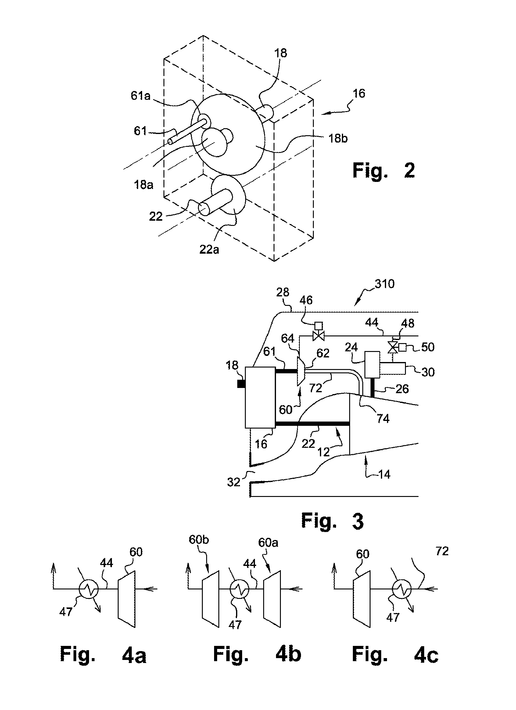
The invention relates to an aircraft turboprop engine (310) comprising at least a low-pressure body (12) and a high-pressure body (14), possibly also an intermediate-pressure body, at least one of said bodies comprising a compressor, the low-pressure body driving a propeller by means of a first gearbox (16), the turboprop engine also comprising means for supplying air to an air-conditioning circuit of an aircraft cabin, characterised in that said supply means comprise at least one compressor (60) of which the rotor (61) is coupled to the low-pressure body, said load compressor (60) including an air inlet (62) connected to means (72) for bleeding air from the compressor of the turboprop engine when all of the aforementioned bodies comprise only a single compressor, or from the compressor of the low-pressure body or the compressor of the intermediate-pressure body of the turboprop engine when all of the bodies comprise at least two compressors.

Description

TECHNICAL FIELD[0001]The present invention relates to the supply of air to an air-conditioning circuit of an aircraft cabin that is equipped with at least one turboprop engine.PRIOR ART[0002]On board an aircraft, it is necessary to have air available in order to be able to perform certain functions, such as the air conditioning of the cockpit and the passenger cabin or the de-icing of certain components of the aircraft. At high altitudes, the oxygen becomes scarcer and the air pressure drops. This involves pressurising the aircraft cabins in order to ensure the comfort and survival of the passengers during a flight. For this purpose, air with a minimum pressure level (in general between 0.8 and 1 bar) and a controlled temperature (regulatory requirement) must be supplied to the air-conditioning circuit. An aircraft is thus equipped with an air-conditioning circuit that is supplied by the engine or engines of the aircraft, which are turboprop engines in the context of the invention.[...

Claims


Application Information

Patent Timeline
Patent Type & Authority Applications(United States)
IPC IPC(8): B64D13/02B64D13/08B64D27/10B64D13/06
CPCB64D13/02B64D13/06B64D2013/0696B64D27/10B64D13/08B64D13/00B64D2013/0618F02C6/206F05B2260/20F05D2220/324F05D2220/325Y02T50/50Y02T50/60F02C6/06F02C7/27F02C9/18F04D29/321F04D29/522F04D29/563F04D29/5833F05D2220/323F05D2240/60F05D2260/4031
Inventor PARMENTIER, NICOLAS CLAUDEFROMENT, PIERRERIDEAU, JEAN-FRANCOISTHORAVAL, BRUNO
Owner SAFRAN POWER UNITS
Learn More