Phase locked loop circuit and method of frequency adjustment of injection locked frequency divider
a phase lock loop and frequency divider technology, applied in the field of phase lock loop circuits, can solve problems such as the inability to operate the frequency division, and achieve the effects of simple circuit configuration, stable operation of frequency division, and simple configuration
- Summary
- Abstract
- Description
- Claims
- Application Information
AI Technical Summary
Benefits of technology
Problems solved by technology
Method used
Image
Examples
first embodiment
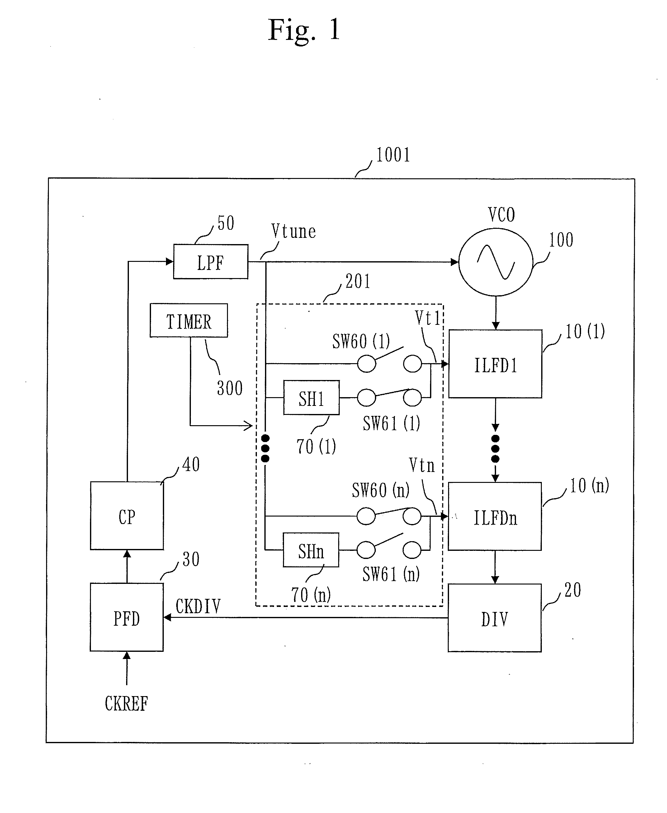
[0026]FIG. 1 is a block diagram illustrating a PLL circuit 1001 of a first embodiment.
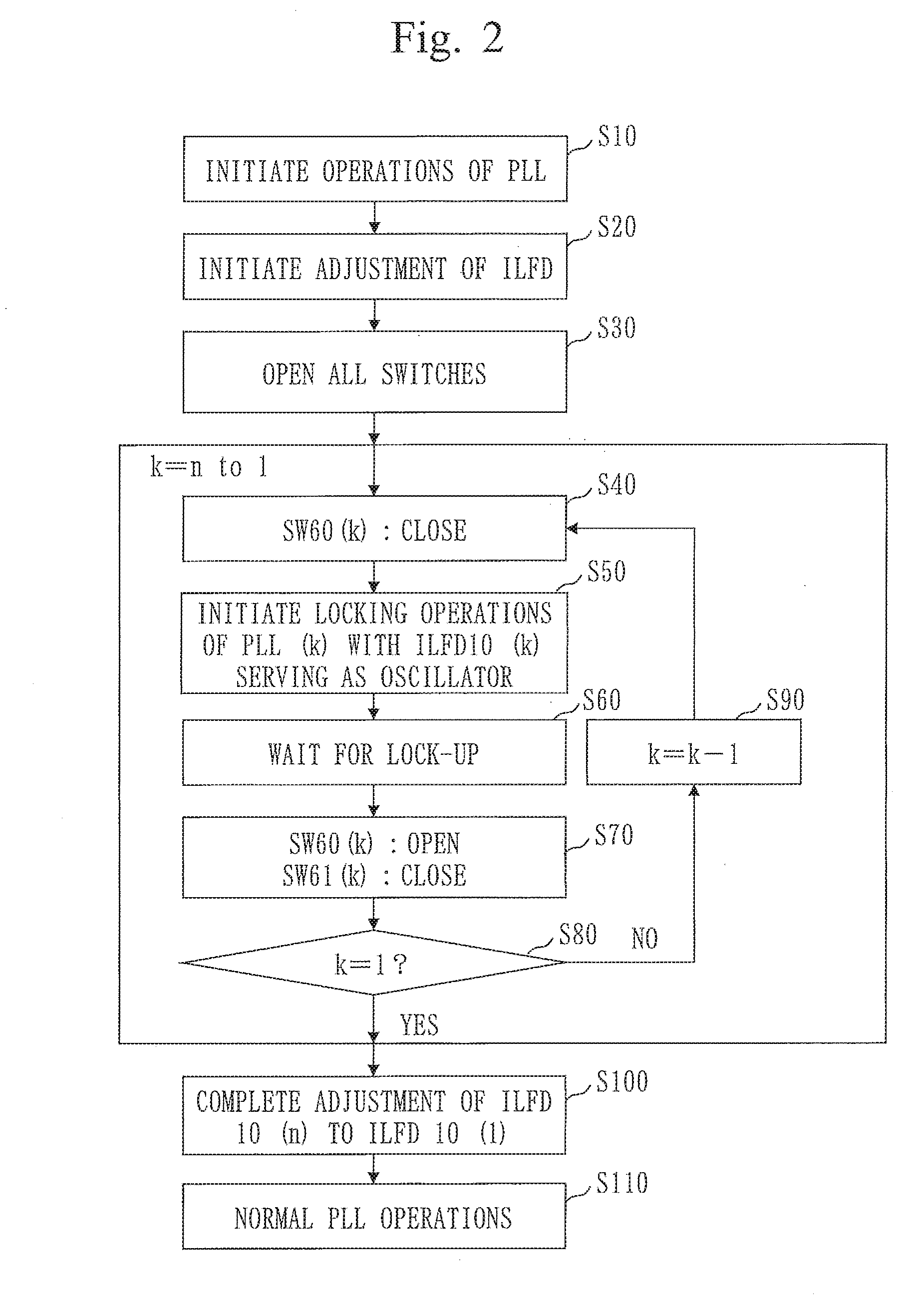
[0027]FIG. 2 is a flowchart illustrating operations of the PLL circuit 1001. The PLL circuit 1001 allows for inputting an oscillator control voltage output from a loop filter to an injection locked frequency divider (ILFD) and configuring a PLL by forming a loop with the ILFD operating as an oscillator, thereby implementing adjustment of a free-run frequency of the ILFD.
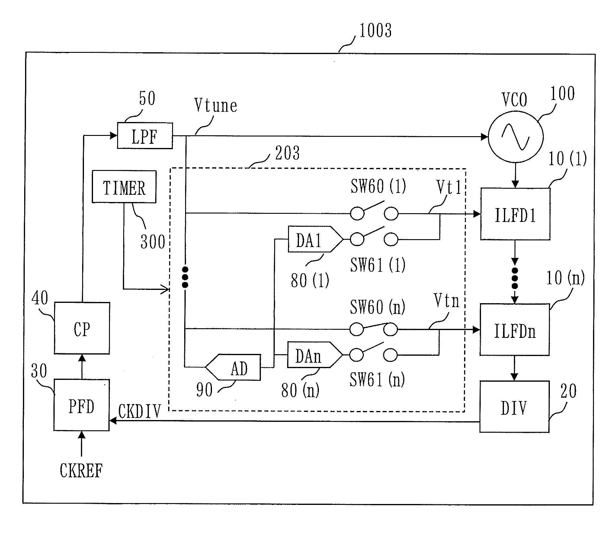
[0028]As in FIG. 1, the PLL circuit 1001 includes n (where n is an integer greater than or equal to 1) injection locked frequency dividers 10 serially connected with each other, a frequency divider 20, a phase frequency detector 30, a charge pump 40, a loop filter 50 (filter), n switches 60, n switches 61, n sample hold circuits 70, a voltage controlled oscillator 100 (oscillator), and a timer circuit 300.
[0029]In the descriptions below,[0030](1) The n injection locked frequency dividers 10 are noted as ILFD 10 (1), ILFD 10 (2), ILF...
second embodiment
[0061]FIG. 6 is a block diagram illustrating a PLL circuit 2000 of a second embodiment. Here, only different points from the PLL circuit 1001 of the first embodiment will be described. In the PLL circuit 2000 of the second embodiment, the LPF 50 is controlled and thereby a cut-off frequency switches between a normal time and a time of ILFD adjustment.
[0062]A convergence time and stability of the PLL are dependent on the cut-off frequency of the loop filter. Therefore, by switching the cut-off frequency of the loop filter, for example by setting a low cut-off frequency at the normal time, phase noise is mitigated and by setting a higher cut-off frequency at the time of adjustment than at the normal time, the convergence time is shortened. In this manner, when the cut-off frequency of the LPF 50 can be changed, response characteristics of the PLL can be maintained in an appropriate manner at each of the normal time and the time of adjustment.
third embodiment
[0063]FIG. 7 is a block diagram illustrating a PLL circuit 3000 of a third embodiment. Here, only different points from the PLL circuit 1001 of the first embodiment will be described. In the PLL circuit 3000 of the third embodiment, the CP 40 is controlled and thereby an output current level switches between a normal time and a time of ILFD adjustment.
[0064]A convergence time and stability of the PLL are dependent on an output current from the CP 40. Therefore, by switching the output current from the CP 40, for example the output current from the CP 40 is set low at the normal time in order to mitigate phase noise and the output current from the CP 40 is set high at the time of adjustment in order to shorten the convergence time. With such switching, response characteristics of the PLL circuit 3000 can be maintained in an appropriate manner at each of the normal time and the time of adjustment.
PUM
 Abstract
Description
Claims
Application Information
 - R&D
- Intellectual Property
- Life Sciences
- Materials
- Tech Scout
- Unparalleled Data Quality
- Higher Quality Content
- 60% Fewer Hallucinations
Browse by: Latest US Patents, China's latest patents, Technical Efficacy Thesaurus, Application Domain, Technology Topic, Popular Technical Reports.
© 2025 PatSnap. All rights reserved.Legal|Privacy policy|Modern Slavery Act Transparency Statement|Sitemap|About US| Contact US: help@patsnap.com


