Multi-speed transmission

a transmission and multi-speed technology, applied in mechanical equipment, transportation and packaging, gearing, etc., can solve the problems of reducing the speed change performance, affecting the transmission performance, so as to improve the fuel efficiency of the vehicle, improve the drivability, and increase the spread

Inactive Publication Date: 2016-11-24
AISIN AW CO LTD +1
View PDF2 Cites 41 Cited by
  • Summary
  • Abstract
  • Description
  • Claims
  • Application Information

AI Technical Summary

Benefits of technology

[0007]With the thus configured multi-speed transmission, first to ninth forward speeds, or first to tenth forward speeds, and a reverse speed can be established by selectively engaging three of the first, second, third, fourth, fifth, and sixth engagement elements. Consequently, it is possible to improve the fuel efficiency of the vehicle on which the multi-speed transmission is mounted by increasing the spread, and to further improve the drivability, that is, the acceleration performance of the vehicle etc., by making the speed ratios of lower speeds higher and making the speed ratios of higher speeds lower. With the multi-speed transmission, in addition, the torque distribution of each of the first to fourth engagement elements can be reduced to make the first to fourth engagement elements lightweight and compact, and to suppress degradation in drag loss in the first to fourth engagement elements. Further, it is possible to improve the controllability of the first to sixth engagement elements by making the torque distribution ratios of the first to sixth engagement elements lower. Thus, with the multi-speed transmission according to some preferred embodiments, it is possible to further improve the fuel efficiency, the drivability, and the speed change performance of the vehicle on which the multi-speed transmission is mounted, and to make the entire device lightweight and compact.

Problems solved by technology

Therefore, in the multi-speed transmission described in Patent Document 1, it is necessary to secure the torque capacity by increasing the axial length or the outside diameter of the clutch, which may incur an increase in size and weight of the entire device and degradation in drag loss in the clutch.
Further, the controllability (hydraulic controllability) of the clutch and the brake with high torque distribution ratios may be degraded, which may lower the speed change performance.

Method used


Image

  • Multi-speed transmission
  • Multi-speed transmission
  • Multi-speed transmission

Examples


Embodiment Construction

[0017]Now, an embodiment will be described with reference to the drawings.

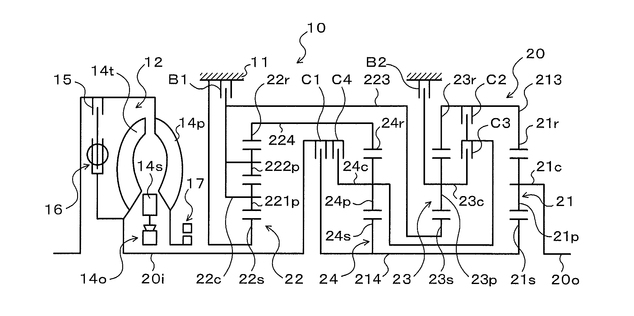
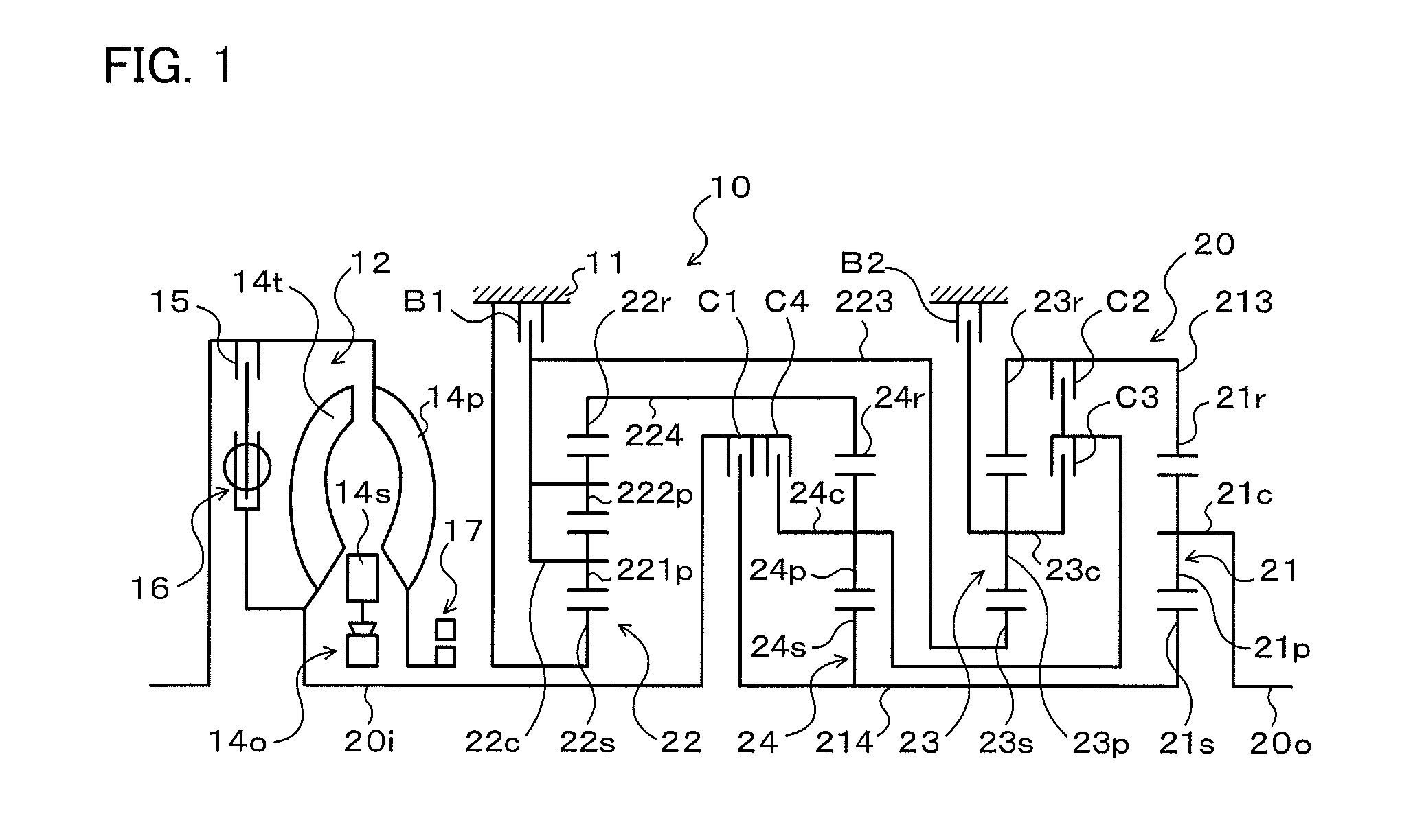
[0018]FIG. 1 illustrates a schematic configuration of a power transfer device 10 that includes an automatic transmission 20 that serves as a multi-speed transmission according to an embodiment. The power transfer device 10 illustrated in the drawing is connected to a crankshaft of an engine (internal combustion engine; not illustrated) that serves as a drive source longitudinally mounted in the front portion of a rear-drive vehicle, and can transfer power (torque) from the engine to left and right rear wheels (drive wheels; not illustrated). As illustrated in the drawing, the power transfer device 10 includes a transmission case (stationary member) 11, a starting device (fluid transmission apparatus) 12, an oil pump 17, and so forth in addition to the automatic transmission 20 which transfers power, which has been transferred from the engine to an input shaft 20i, to an output shaft 20o with the speed of the p...


PUM


Abstract

An automatic transmission includes a single-pinion first planetary gear, a double-pinion second planetary gear, a single-pinion third planetary gear, a single-pinion fourth planetary gear, clutches C1, C2, C3, and C4, and brakes B1 and B2. First to ninth forward speeds and a reverse speed are established by engaging three of the clutches C1 to C4 and the brakes B1 and B2 and disengaging the remaining three clutches and brakes.

Description

I. TECHNICAL FIELD[0001]Preferred embodiments relate to a multi-speed transmission that transfers power, which has been transferred from a motor of a vehicle to an input member, to an output member with the speed of the power changed.BACKGROUND ART[0002]There has hitherto been known a multi-speed transmission that includes four single-pinion planetary gears, four clutches, and two brakes and that provides forward speeds from a first speed to a ninth speed and a reverse speed (see Patent Document 1, for example). With such a multi-speed transmission, the power transfer efficiency, that is, the fuel efficiency of a vehicle on which the multi-speed transmission is mounted, and the drivability, that is, the acceleration performance of the vehicle, can be improved as the spread (gear ratio width=the gear ratio of the lowest speed / the gear ratio of the highest speed) is increased.RELATED-ART DOCUMENTSPatent Documents[0003][Patent Document 1] United States Patent Application Publication No...

Claims


Application Information

Patent Timeline
Patent Type & Authority Applications(United States)
IPC IPC(8): F16H3/66
CPCF16H3/666F16H3/66F16H2200/0008F16H2200/2046F16H2200/0069F16H2200/2012F16H2200/0065F16H2200/2097
Inventor KATO, TAKAYOSHIMORIMOTO, TAKASHIAOKI, TOSHIHIKOKATO, HIROSHIKASUYA, SATORUMIYAZAKI, TERUFUMIMORISE, MASARUOITA, SHINJI
Owner AISIN AW CO LTD
Why Eureka
Try Eureka