Front end circuit and wireless communication device

a front-end circuit and wireless communication technology, applied in the direction of antenna details, electrical equipment, antennas, etc., can solve the problems of affecting the reception sensitivity of high-frequency characteristics, the distortion of signals by the online presence of active elements, etc., and achieve the effect of suppressing the degradation of high-frequency characteristics

Inactive Publication Date: 2016-11-24
MURATA MFG CO LTD
View PDF6 Cites 21 Cited by
  • Summary
  • Abstract
  • Description
  • Claims
  • Application Information

AI Technical Summary

Benefits of technology

[0020]According to the front end circuit of this disclosure, it is possible to achieve matching with an antenna across a wide frequency band and suppress degradation in high-frequency characteristics caused by the influence of transmission signal harmonics.

Problems solved by technology

However, there is a problem in that the nonlinearity of an active element distorts signals, and antenna tuners having active elements have been sources of harmonics of the transmission signals.
In such a case, harmonics produced in the antenna tuner can leak to a high frequency band-side reception circuit and cause degradation in high-frequency characteristics such as reception sensitivity and the like.

Method used


Image

  • Front end circuit and wireless communication device
  • Front end circuit and wireless communication device
  • Front end circuit and wireless communication device

Examples


first embodiment

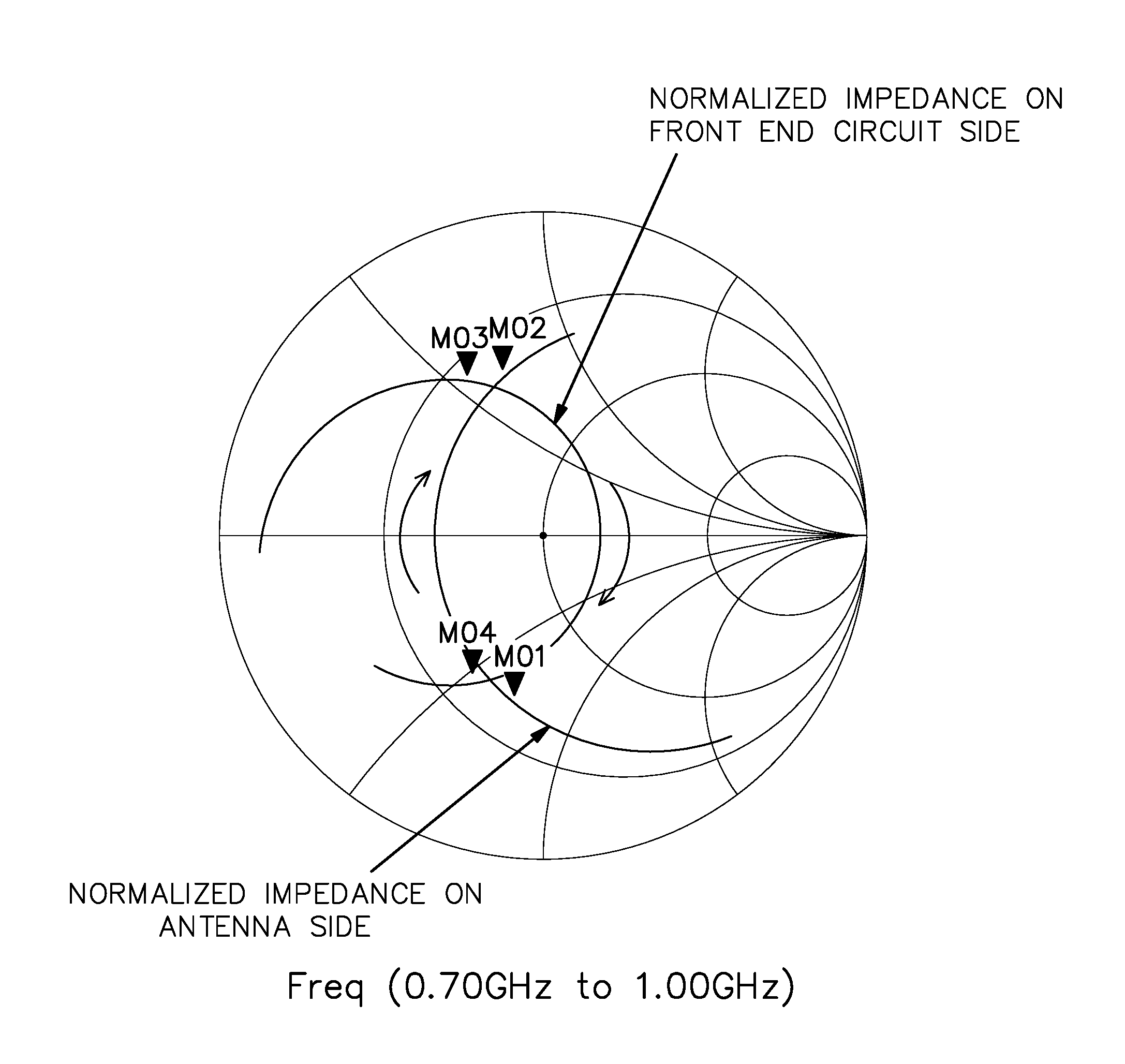
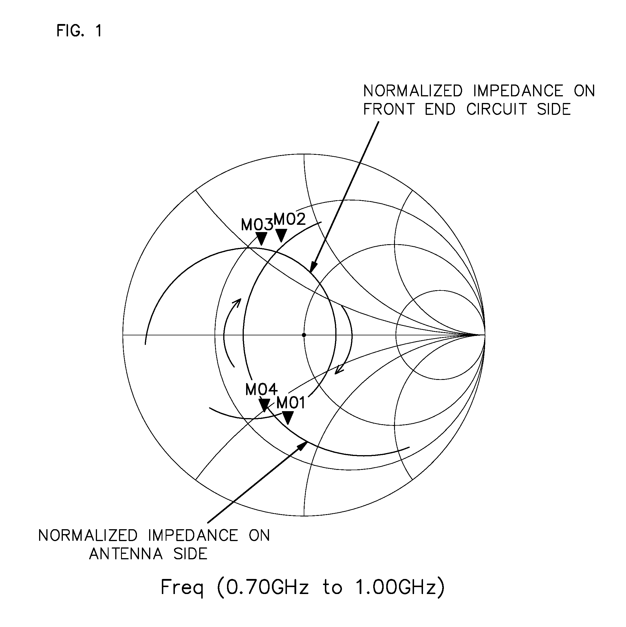
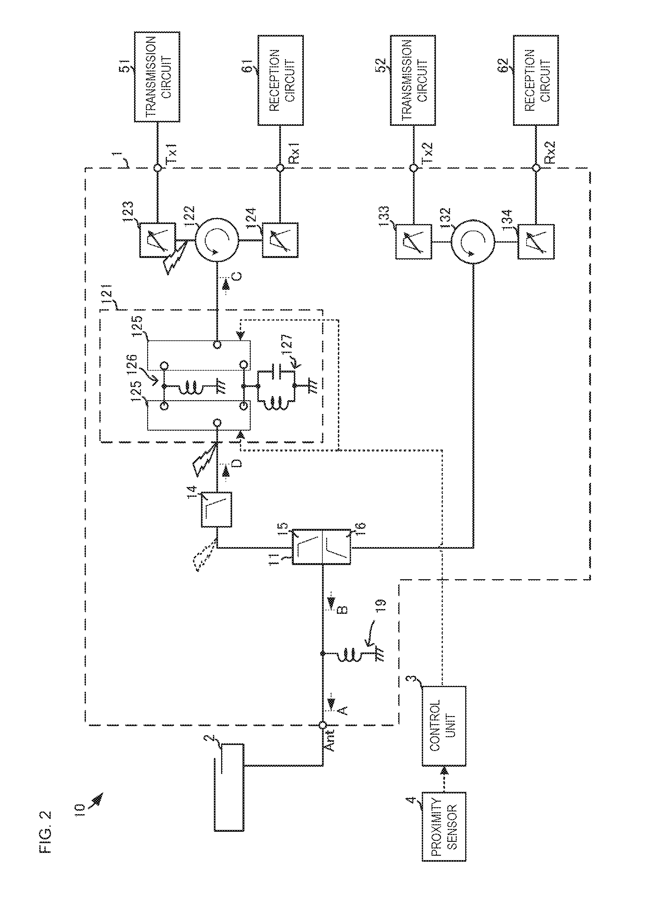
[0034]FIG. 2 is a circuit block diagram illustrating a front end circuit and a wireless communication device according to a first embodiment. A wireless communication device 10 according to the present embodiment transmits and receives using a plurality of communication bands included in a first frequency band (a low-frequency band) and a plurality of communication bands included in a second frequency band (a high-frequency band). In the case of LTE, for example, a low-frequency band-side communication band is a communication band of approximately 1 GHz or lower. In the case of LTE, for example, a high-frequency band-side communication band is a communication band of approximately 1.4 GHz or higher.

[0035]The wireless communication device 10 includes a front end circuit 1, an antenna 2, a control unit 3, a proximity sensor 4, transmission circuits 51 and 52, and reception circuits 61 and 62.

[0036]The front end circuit 1 transmits and receives in each communication band through the an...

second embodiment

[0062]A wireless communication device 10D and a front end circuit 1D according to a second embodiment of the present disclosure will be described next. FIG. 3 is a circuit block diagram illustrating the wireless communication device 10D and the front end circuit 1D according to the present embodiment. The wireless communication device 10D and the front end circuit 1D omit the diplexer 11 described in the first embodiment, and are provided with an antenna port Ant1 for circuits on the low-frequency band side and an antenna port Ant2 for circuits on the high-frequency band side. In the front end circuit 1D, the harmonic filter 14 is connected directly to the antenna port Ant1, and the circulator 132 is connected directly to the antenna port Ant2. The antenna matching circuit 19 is provided only for the antenna port Ant1. The two power supply points, one for low frequencies and one for high frequencies, are provided for the antenna 2. The antenna 2 may be constituted of a single elemen...

third embodiment

[0079]A wireless communication device 10A and a front end circuit 1A according to a third embodiment of the present disclosure will be described next. FIG. 6 is a circuit block diagram illustrating the wireless communication device 10A and the front end circuit 1A according to the present embodiment. The wireless communication device 10A and the front end circuit 1A include matching circuits 126A and 127A instead of the matching circuits 126 and 127 described in the first embodiment. The matching circuits 126A and 127A are variable impedance circuits having variable-reactance active elements such as digital tuning capacitors (DTC).

[0080]When the current state is determined to be the antenna non-proximate state, the control unit 3 controls the variable matching circuit 121 to cause the active switch element 125 to connect the matching circuit 126A to the signal path. Meanwhile, when the current state is determined to be the antenna proximate state, the control unit 3 controls the var...


PUM


Abstract

A front end circuit and a wireless communication device capable of achieving matching with an antenna across a wide frequency band and capable of suppressing degradation in high-frequency characteristics caused by the influence of transmission signal harmonics is provided. A front end circuit includes a variable matching circuit connected to a low-frequency band transmission port side of a diplexer and a harmonic filter connected between the variable matching circuit and the diplexer. The harmonic filter has a pass band that overlaps with a low-frequency band-side communication band and a stop band that overlaps with a harmonic frequency of the low-frequency band-side communication band.

Description

BACKGROUNDTechnical Field[0001]The present disclosure relates to a front end circuit that separates signals in communication bands within a predetermined frequency band, and to a wireless communication device that includes the same.[0002]At present, wireless communication devices such as cellular phone terminals are configured to use multiple types of communication bands. A front end circuit is used in a wireless communication device in order to handle such a variety of communication bands using a single or a small number of antennae. The front end circuit is provided with, for example, an antenna matching circuit for ensuring matching with an antenna, and a separator circuit that separates signals in high-frequency communication bands and signals in low-frequency communication bands.[0003]The antenna matching circuit has been configured to bring an antenna-side normalized impedance in a predetermined communication band, as viewed from the separator circuit side, to the vicinity of ...

Claims


Application Information

Patent Timeline
Patent Type & Authority Applications(United States)
IPC IPC(8): H01Q5/335H01Q1/24
CPCH01Q1/243H01Q5/335H04B1/525
Inventor ONAKA, KENGOTANAKA, HIROYAOBIYA, HIDENORINAKAIKE, YUKINAKAJIMA, REIJI
Owner MURATA MFG CO LTD
Why Eureka
Try Eureka