
Process For Dissolving Aluminum For Recovering Nuclear Fuel

Active Publication Date: 2016-12-01
THE UNITED STATES AS REPRESENTED BY THE DEPARTMENT OF ENERGY +1
View PDF0 Cites 0 Cited by
  • Summary
  • Abstract
  • Description
  • Claims
  • Application Information

AI Technical Summary

Benefits of technology

The patent describes a way to control the dissolution of aluminum in an acid bath to affect off-gas production. Specifically, the process can reduce the rate at which hydrogen gas is produced and minimize the amount of hydrogen gas in the off-gas. This results in a more efficient process and reduced energy consumption.

Problems solved by technology

Fuel elements, including fuel rods in nuclear reactors, become unusable not so much on account of actual depletion of the fissionable fuel values, but because of the accumulation within the element of fission products.
These fission products can interfere with the neutron flux within the reactor.
Thus, the off-gas generation rate is never constant.
The mechanisms that impact off-gas concentrations and species that produce the above gases during the course of dissolution are complex and are not well understood.
Spikes in the generation of off-gases, however, can produce significant amounts of hydrogen gas which may drift above safety levels in the processing plant.
The process proposed in the '658 patent, however, has had limited success.

Method used


Image

  • Process For Dissolving Aluminum For Recovering Nuclear Fuel
  • Process For Dissolving Aluminum For Recovering Nuclear Fuel
  • Process For Dissolving Aluminum For Recovering Nuclear Fuel

Examples


example 1

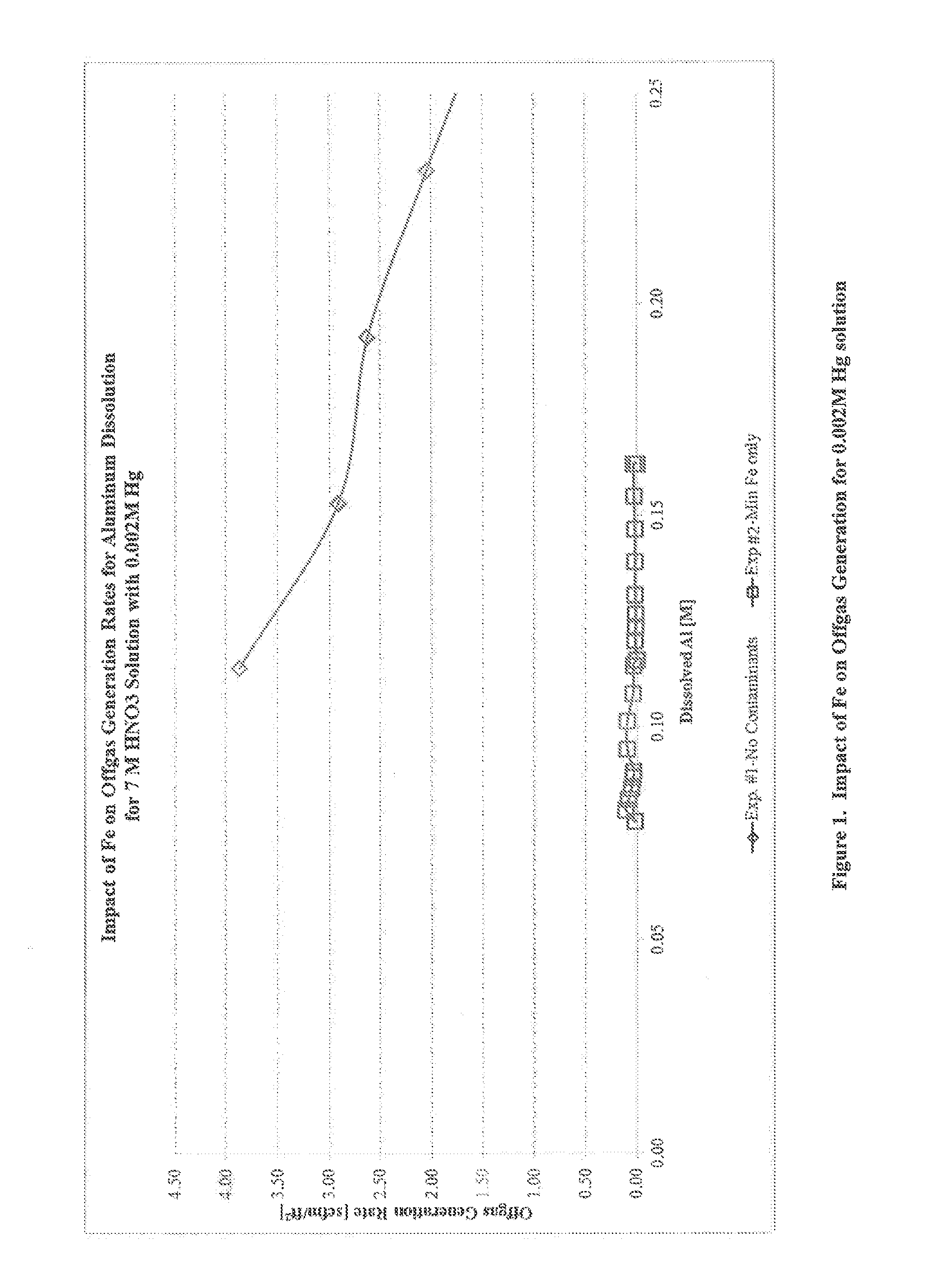
[0035]Single-impurity scoping experiments to determine the influence of individual contaminants on off-gas rate were initially performed using Al-1100 alloy coupons. A series of four Al-1100 coupons were cut to the approximate dimensions of 19×11×3 mm. A 1 / 16 inch hole was drilled into each coupon in order to fasten each coupon to the glass rods used to lower them into a dissolving nitric acid solution. The coupons were lightly sanded, washed with soap and water, and then weighed and measured. Each coupon weighed approximately 1.7 g and had a surface area of approximately 6 cm2. Each coupon was tied by Teflon™ string through the 1116 inch hole to a glass rod on the dissolver apparatus that was labeled with the coupon position number for coupon identification.

[0036]A dissolver apparatus and off-gas collection system were assembled in a chemical hood. The dissolver apparatus contained a boiling flask with multiple ports, a condenser, an in-line gas sample glass bulb, and a water-subme...

example 2

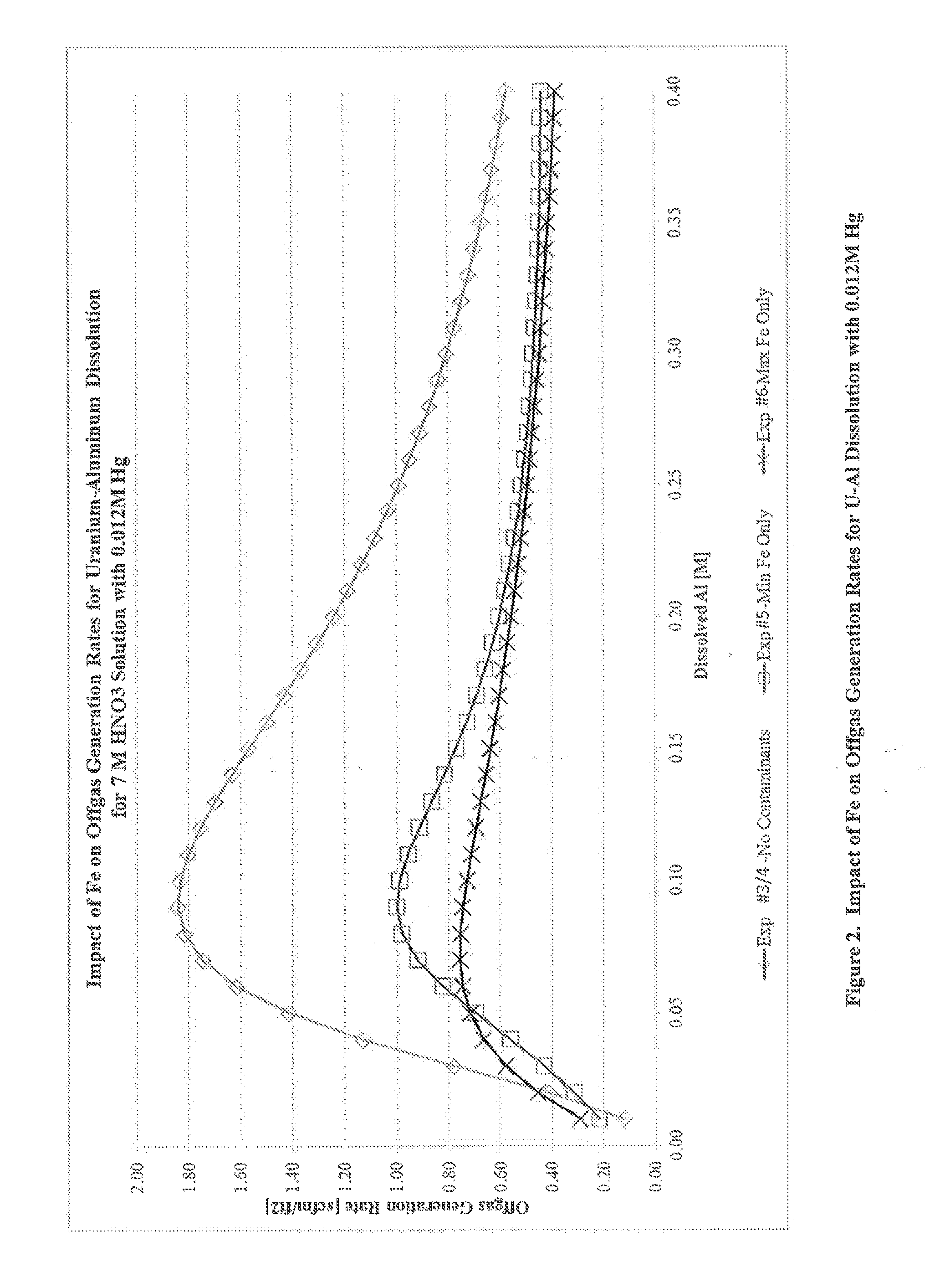
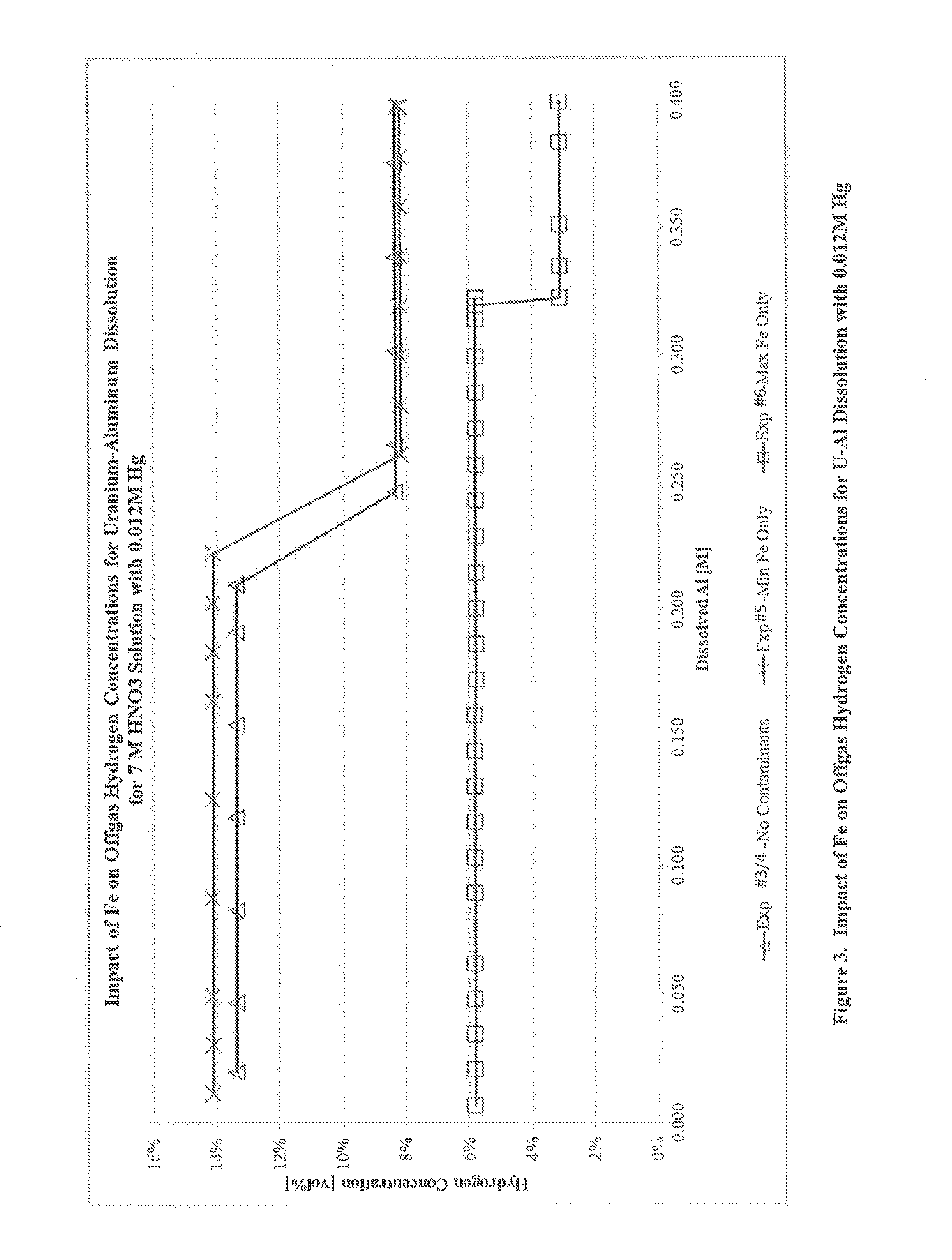
[0041]Another series of experiments were performed to determine the impact of Fe on off-gas generation rates for uranium-aluminum dissolution at higher concentrations of Hg. A series of four 30 wt % U—Al alloy coupons, cut to 20×12×3 mm with a mass of 1.6-2.1 g, were prepared as described in Example 1.

[0042]Experiment 3 was conducted using a method analogous to that of Example 1 with a dissolving solution of 7 M HNO3, 0.1 M KF, 0.012 M Hg, and no Fe contamination. Hg was initially present in the solution, and the solution was heated to 100° C. before lowering the first coupon. The concentration of hydrogen in the off-gas was measured using gas chromatography.

[0043]Experiment 4 was conducted using a dissolving solution of 7 M HNO3, 0.1 M KF, 0.012 M Hg, and no Fe contamination. Approximately 130 mL of dissolving solution was weighed and added to the dissolver flask containing a Teflon™ stir bar. The solution containing all components except Hg was then heated to 100° C. A syringe pum...


PUM

PropertyMeasurementUnit
Fractionaaaaaaaaaa
Fractionaaaaaaaaaa
Fractionaaaaaaaaaa

Abstract

A process for controlling the dissolution of a metal in an acid bath is described. The metal may comprise aluminum and the acid bath may contain a metal catalyst that causes the metal to dissolve. In order to control the rate of dissolution and / or the amount of gas evolved during the process, an iron source is added to the bath. In one embodiment, the process can be used to dissolve aluminum contained in spent fuel assemblies for recovering a nuclear fuel, such as uranium.

Description

BACKGROUND[0001]A unique characteristic of nuclear energy is that used fuel may be separated from other components and reused as new fuel. For instance, the nuclear materials contained in a spent rod from a nuclear power plant can be reprocessed and reused to produce new fuel rods. Practically all nuclear materials, including uranium and plutonium, can be reprocessed in this manner.[0002]Fuel elements, including fuel rods in nuclear reactors, become unusable not so much on account of actual depletion of the fissionable fuel values, but because of the accumulation within the element of fission products. These fission products can interfere with the neutron flux within the reactor. Consequently, fuel elements are withdrawn from the reactor long before the fuel values are anywhere near to being completely consumed. The withdrawn or used nuclear fuel (sometimes referred to as spent fuel rods) have significant fuel value. At the same time, it is desirable to recover the valuable by-produ...

Claims


Application Information

Patent Timeline
IPC IPC(8): C22B21/00
CPCC22B21/0061C22B21/0023G21C19/44Y02E30/30Y02W30/50
Inventor ALMOND, PHILIP M.DANIEL, WILLIAM E.RUDISILL, TRACY S.
Owner THE UNITED STATES AS REPRESENTED BY THE DEPARTMENT OF ENERGY
Features
  • Generate Ideas
  • Intellectual Property
  • Life Sciences
  • Materials
  • Tech Scout
  • Unparalleled Data Quality
  • Higher Quality Content
  • 60% Fewer Hallucinations
Learn More