Plasma generator and thermal electron emitter
- Summary
- Abstract
- Description
- Claims
- Application Information
AI Technical Summary
Benefits of technology
Problems solved by technology
Method used
Image
Examples
modification 1
[0067](Modification 1)
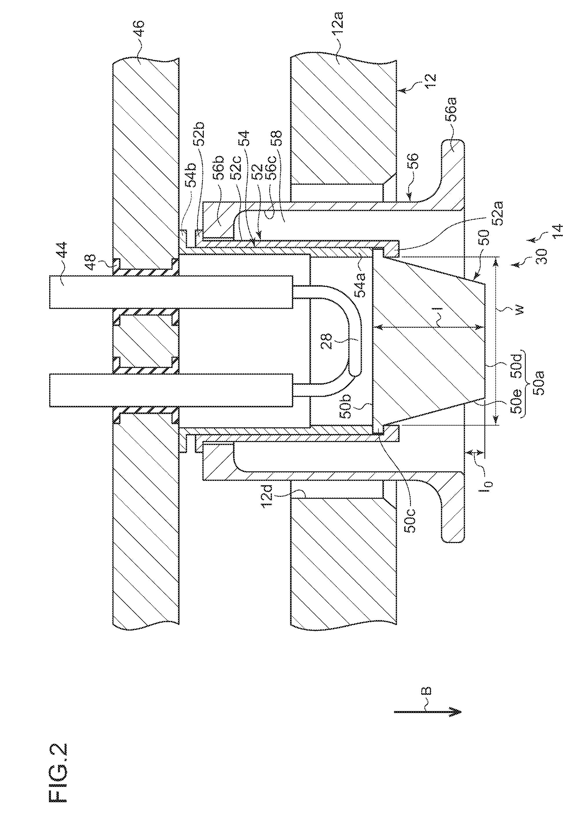
[0068]FIG. 6 is a cross-sectional view illustrating a configuration of a thermal electron emitter 214 according to a modification. A cathode 230 according to the modification differs from that of the aforementioned embodiment in that the cathode 230 includes a cathode cap 250 having a hemispherical shape. Next, the present modification will be described while focusing on the difference from the aforementioned embodiment.
[0069]The cathode cap 250 includes a thermal electron emitting surface 250a, a heat inflow surface 250b, and a flange 250c. The cathode cap 250 has a hemispherical shape or a shape obtained by cutting a part of a sphere or spheroid, as illustrated. Therefore, the cathode cap 250 has a shape of which a width w in the radial direction becomes gradually smaller toward the inside of the arc chamber 12. The thermal electron emitting surface 250a is constituted of a convex curved surface, such as a spherical surface or an spheroidal surface, and a cur...
modification 2
[0071](Modification 2)
[0072]FIG. 7 is a cross-sectional view illustrating a configuration of a thermal electron emitter 314 according to a modification. A cathode 330 according to the modification differs from that of the aforementioned embodiment in that the cathode 330 includes a cathode cap 350 having a shape in which a convex curved surface is added to an upper surface of a truncated cone. Next, the present modification will be described while focusing on the difference from the aforementioned embodiment.
[0073]The cathode cap 350 includes a first portion 351 having a truncated conical shape, and a second portion 352 having a shape obtained by cutting apart of a sphere. The first portion 351 has a heat inflow surface 350b facing a filament 28, a side surface 350e constituted of a conical surface, and a flange 350c protruding from the heat inflow surface 350b outward in the radial direction. The second portion 352 has a front surface 350d constituted of a convex curved surface, su...
modification 3
[0075](Modification 3)
[0076]FIG. 8 is a cross-sectional view illustrating a configuration of a thermal electron emitter 414 according to a modification. A cathode 430 according to the present modification differs from the aforementioned embodiment in that the cathode 430 includes a cathode cap 450 having rotationally symmetric shape in which an inclination of a side surface 450e with respect to the axial direction is changed in a stepwise manner. Next, the present modification will be described while focusing on the difference from the aforementioned embodiment.
[0077]The cathode cap 450 includes a first portion 451 having a cylindrical shape, and a second portion 452 having a truncated conical shape and a third portion 453, which have a truncated conical shape. The first portion 451, the second portion 452, and the third portion 453 are sequentially stacked toward the inside of the arc chamber 12. The first portion 451 has a heat inflow surface 450b facing a filament 28, a first sid...
PUM
 Abstract
Description
Claims
Application Information
 - R&D
- Intellectual Property
- Life Sciences
- Materials
- Tech Scout
- Unparalleled Data Quality
- Higher Quality Content
- 60% Fewer Hallucinations
Browse by: Latest US Patents, China's latest patents, Technical Efficacy Thesaurus, Application Domain, Technology Topic, Popular Technical Reports.
© 2025 PatSnap. All rights reserved.Legal|Privacy policy|Modern Slavery Act Transparency Statement|Sitemap|About US| Contact US: help@patsnap.com


