Method for preparing a fuel cell electrode membrane assembly by means of electrodeposition

a fuel cell and electrode membrane technology, applied in the direction of electrolytic coatings, electrical devices, coatings, etc., can solve the problems of lack of electronic conductivity, relatively complex structure preparation, lack of homogeneity of particle distribution, etc., and achieve the effect of increasing the developed area

Inactive Publication Date: 2016-12-01
COMMISSARIAT A LENERGIE ATOMIQUE ET AUX ENERGIES ALTERNATIVES
View PDF3 Cites 0 Cited by
  • Summary
  • Abstract
  • Description
  • Claims
  • Application Information

AI Technical Summary

Benefits of technology

[0038]Anionic precursors are preferred to avoid a possibly contamination of the membrane by exchanges between protons and cations of the transition metal.
[0045]The potential cycling method enables to make sure by observation of curves of E vs. i that the reduction of the ions of transition metal M (for example, Pt), and thus the presence of particles of metal M at the membrane surface, is effective.
[0051]a humectant (glycerol or ethylene glycol, for example), which especially ensures a good wettability at the surface of the deposit. It generally has a high boiling temperature, and enables to keep water in the active layer, which favors the ion transport through the deposit during the reduction of the transition metal precursor.
[0053]The presence of electronically-conductive particles in the composition containing a transition metal precursor especially enables to increase the developed area without for all this sealing or clogging the accessibility to the membrane.

Problems solved by technology

However, it is not electronically-conductive.
However, this type of catalytic layer is prepared chemically, which has as a main disadvantage a lack of homogeneity of the particle distribution;the nanostructuring of the electrode material, which enables to increase the surface area of the electrode material accessible to the reactants (O2, electrons, protons).
However, such structures are relatively complex to prepare, which makes them improper for commercialization for the time being;the electrodeposition of platinum particles.
However, this method is limited to the electrodeposition of platinum on a carbon gas diffusion electrode (CCB method), by reduction of a platinum solution.

Method used


Image

  • Method for preparing a fuel cell electrode membrane assembly by means of electrodeposition
  • Method for preparing a fuel cell electrode membrane assembly by means of electrodeposition
  • Method for preparing a fuel cell electrode membrane assembly by means of electrodeposition

Examples


Embodiment Construction

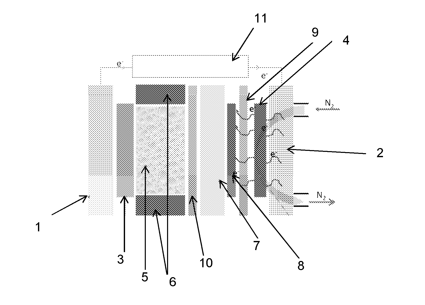
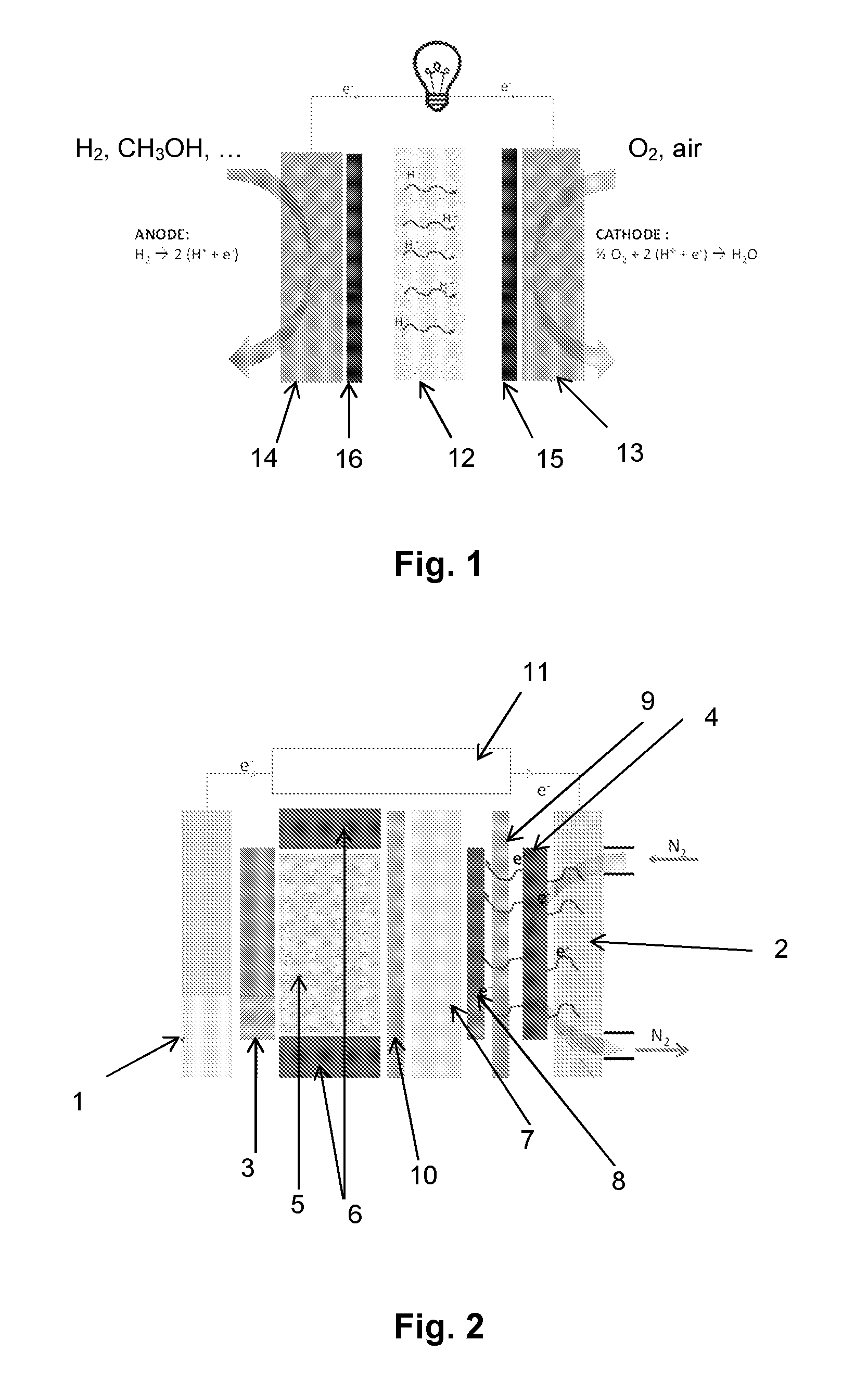
[0083]FIG. 2 illustrates an electrodeposition cell capable of allowing the implementation of the method according to the present invention.

[0084]This cell comprises:[0085]a current or voltage generator (11),[0086]two current collectors, (1) and (2),[0087]an anode (3) (gate made of corrosion-resistant metal, of tantalum, for example),[0088]a cathode (carbon, for example) (4),[0089]an electrolyte (H2SO4) (5), arranged between the anode (3) and the cathode (4), in a cell closed, in particular, by seals (6).

[0090]Typically, anode (3) is porous, so that inert gas (nitrogen or argon, for example) can flow to avoid any oxygen reduction reaction at the anode (3).

[0091]In the method of forming a MEA or a half-MEA according to the present invention, a main surface of a proton exchange membrane (7) is covered with a composition of a transition metal salt, advantageously based on platinum.

[0092]The deposit (8) is dried during the deposition phase.

[0093]The proton exchange membrane (7) is then p...


PUM

PropertyMeasurementUnit
temperatureaaaaaaaaaa
overvoltageaaaaaaaaaa
wt. %aaaaaaaaaa

Abstract

A method of preparing by electrodeposition a membrane electrode assembly for a fuel cell, including the steps of:depositing a composition containing at least one precursor of a transition metal and electronically-conductive particles, on a main surface of a proton exchange membrane;drying the deposit;positioning the proton exchange membrane in an electrodeposition cell;reducing the transition metal precursor made of transition metal particles having a degree of oxidation equal to 0, by flowing of an electric current through the electrodeposition cell;obtaining a membrane electrode assembly having its proton exchange membrane including a main surface containing particles of the transition metal having a degree of oxidation equal to 0.

Description

DOMAIN THE INVENTION[0001]The invention relates to a method of preparing by electrodeposition a membrane electrode assembly for a fuel cell, the membrane being a proton exchange membrane.[0002]The field of use of the present invention more particularly relates to the conversion of chemical energy into electric energy and in the form of heat.BACKGROUND[0003]Fuel cells, and particularly PEMFCs (proton exchange membrane fuel cells), are relatively attractive due to their high theoretical efficiency and to the non-polluting nature of the reaction byproducts.[0004]Generally, a fuel cell comprises a MEA (membrane electrode assembly) such as that illustrated in FIG. 1. The proton exchange membrane (12) is in contact with a cathode and an anode hosting the reactions ensuring the cell operation, that is, the reduction of the oxidizer (oxygen, air) and the oxidation of the fuel (hydrogen, methanol . . . ), respectively.[0005]The electrodes (cathode and anode) are generally formed of a catalyt...

Claims


Application Information

Patent Timeline
Patent Type & Authority Applications(United States)
IPC IPC(8): H01M4/88C25D15/00H01M4/92C25D5/56C25D3/50
CPCH01M4/881C25D5/56C25D3/50C25D15/00H01M4/8853H01M4/92H01M4/885Y02E60/50
Inventor FOUDA-ONANA, FREDERIC
Owner COMMISSARIAT A LENERGIE ATOMIQUE ET AUX ENERGIES ALTERNATIVES
Why Eureka
Try Eureka